Relays are flexible switches in electronic circuits. There are different kinds, including electromechanical, solid-state, reed, and thermal relays. Each type has its own uses, benefits, and drawbacks.
We have already studied about what is Relay and Relay Operation in the earlier post. Now let us see different types of relays and how to drive the relay. This article describes you the different types of relays like latching relay, reed relay, polarized relay and so on.
Types of Relays:
Here is the list of various types of relays, their working and applications.
1. Latching Relay:
These relays are also called as impulse relay, stay relays or keep relays as they continue the process what they are doing in the last state when the power is switched off. This mechanism can be achieved with the solenoid which operates in ratchet and cam method. In this method power is consumed only for a particular time. Hence these relays are more preferable than other relays. These relays operate in bistable mode. Hence they have two stable states.
2. Reed Relay:
This type of relays is more preferable in contacts. These relays have low switching voltage and current ratings. These are famous because of their switching speeds. You need to keep these relays inside a vacuum or inert gas to protect from atmosphere.
3. Polarized Relay:
Polarized relays work only when the current flows through the coil in one direction. This relay has a diode in series with coil. This diode blocks the current in other direction. The importance is given to this relays based on its sensitivity. They played major roles in telephone exchanges. This relays are also used in telegraphic distortion.
4. Biased Relays:
This relays have a permanent magnet above the armature. This relay is operates when the current through the coil establishes a force which opposes the magnet. If the established force is in the same direction with magnet then relay will not work, even if you apply a large current through the coil.
5. Buchholz Relay:
Generally these relays are used for safety purpose. These relays are used to know the amount of gas present in the large oil filled transformers. These relays produce warning if it senses fast production or slow production of gas in transformer oil.
Related Post: Automatic Street Light Control Circuit using LDR and Relays.
6. Overload Protection Relay:
As the name indicates, these relays are used to prevent the electrical loads from damages by short circuits and over currents and abnormal voltages. In this relays a heating element is placed in series with the motors. Thus when over heat occurs the heating element which is connected to the motor heats up and in turn releases the spring to operate the contacts of the relay.
7. Solid State Relay (SSR):
As the name implies, these are designed with solid state components. These are high reliable as they do not have any moving objects in their design. The basic element in solid state relay is output switch or a triac but more often back to back SCRs. As there is no moving parts these are used in the applications where sparking is major issue.
8. Solid State Contactor Relay:
These relays provide the features of both SSR relays and contactor relays. These relays designed for the correct on – off cycles and they have good heat sink. As a result these relays have number of advantages.
9. Inverse Definite Minimum Time Relay (IDMT Relay):
This relay works based on induction principle. This relay has copper or aluminium disc which rotates between damping magnet and electro magnet. Fluxes induce the currents in the disc which produce rotational torque. This disc rotates to a point where it operates the contacts that break the circuit and remove the fault connection.
10. Differential Relay:
Differential relays are used to check the Dissimilarity between input and currents. The distinction between currents may be in magnitude or in phase or in both. For good operation magnitude and phase angle variations should be zero. If there is any unbalance between input and output currents then relay will actuate.
Relay Driver Circuit:
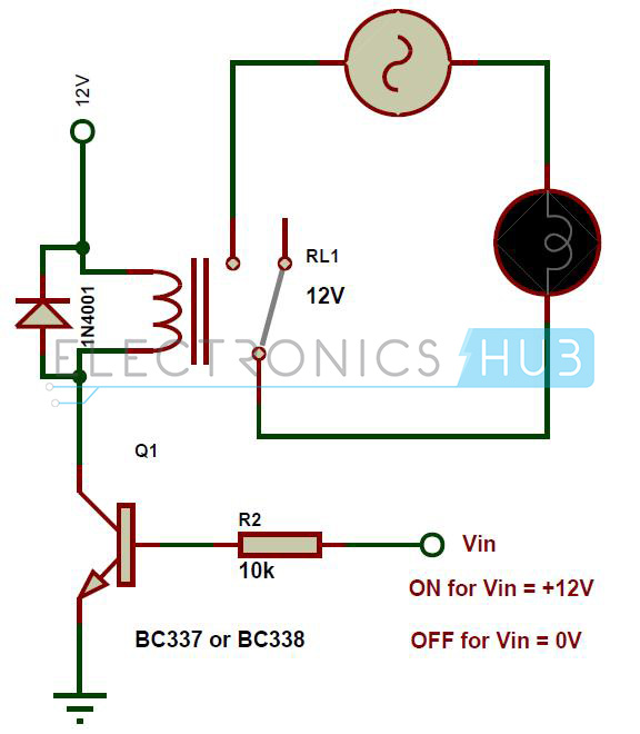
Here is the simple NPN Transistor circuit to drive the relay. We can use less power to drive the relay. We have to make sure that base gets enough current to turn on the transistor. If the transistor gets enough base current then the transistor conducts and relay energizes. When there is no base voltage, the transistor is in open thus blocking the current through coil of the relay.
Here the diode 1n4001 or 1n4007 is connected across the relay, used to protect the transistor from damage due to the back emf generated in the relay coils when transistor is in off. Base resistor is used to set current to the base of the transistor.
Now let us see how to choose the value of R1. Say relay needs 50mA current to the coil to pull the armature and assume coil has resistance of 240 ohm. To turn on the transistor the base current should be greater than the collector current divided by current gain hfe. As the BC337 or BC338 has a minimum current gain of 100 at 100mA. So we need to provide the base current of at least 50mA/100 = 0.5mA.
In practice it is better to double the value, say 1mA of base current. If the input voltage Vin is switching between 0V and 12V. Ib = 12/1mA =12K. So it is better to use 10k resistor.

One Response
For Relay Driver Circuit
If we use PNP transistor instead of NPN then what will be the input to turn ON and turn OFF a relay ?