Generally a transformer is an electrical device or machine which inductively transfers the electrical power operating at a particular current and voltage of one circuit to the other circuit which is operating at different current and voltage level. Most of the transformers are manufactured such that their characteristics must match for special application requirements such as constant current, constant voltage, higher impedance, etc.
The most common types of transformers found in electrical transmission systems, industries and electronic applications include power transformers, instrument transformers, tap changing transformers, auto transformers, RF transformer, audio transformers, etc. They all are different in size, ratings and shape with one another but the basic principle of operation of all these are same. The various types of transformers are discussed in this article so let us have a look on them.
Different Types Of Transformers
Power Transformer
Some of the power transformers are used in generating stations, substations and power transmission lines for either stepping down or stepping up the voltage. By using step-up power transformer, the voltage level in the transmission line is increased, thereby low current flows through the line. Therefore, I2R losses in the transmission lines are reduced. The step-down power transformers are used to supply loads in industries at its rated voltages.
Some of the power transformers also supply the power to the electronic circuits. The power transformer can be single or three phase units based on the application it is employed for. With respect to the unique features of tap changing transformer, auto transformer and distribution transformers are generally belongs to the family of power transformers. Some power transformers are discussed below.
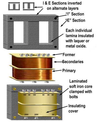
Laminated Core Type Transformer
These are most commonly used transformers and are available from milliwatts to megawatts range. These types of transformers are used in electric power transmission and also in appliances to supply the low voltage. This transformer consists of a laminated core to reduce the eddy currents. A core of thin steel or CRGO or CRNGO ‘E’ and ‘I’ laminations are used for low and high power transformers which can be single or three phase transformers. These laminations are clamped together with bolts. Both primary and secondary windings are wound on a former and are placed around the central limb of the core. These transformers use split bobbin to provide high insulation between the windings for small appliances. Between the primary and secondary, shields may be used to reduce the electromagnetic interference.
Toroidal Core Transformers
This type of transformer offers many advantages over laminated core transformer that it provides quite and efficient operation with reduced stray or external magnetic fields. Due to less weight and small size, these are easily designed for any application operating either low or high voltage. A highly efficient donut shaped core is used which is made from grain oriented silicon iron and is cut to form a ribbon of steel. This core is further wrapped by copper windings like a very tight clock spring. Compared to the EI laminated core transformer, toroidal core transformers are more expensive. However, for a given rating a smaller and lighter will be the toroidal transformer compared with EI laminated type transformer. Also, it provides less leakage of magnetic field and higher efficiency. These are available from a few tens of VA’s to thousands of VA’s. Mostly, they come with center single hole mounting by a bolt with washers and rubber pads.
Auto Transformer
Auto transformers are different from standard two or three winding transformer as it contains only a single winding that acts as both primary and secondary. In this, the part of this single winding is common for both primary and secondary and hence these are electrically connected (two windings are electrically isolated in case of traditional transformer). So this transformer works on conduction as well as induction. In this, a laminated core is wound by a single winding and part of this winding is divided into primary and secondary.
These are classified into step-up and step-down auto transformer. In step-down auto transformer, full winding acts as primary and the part of it act as secondary and hence voltage induced in the secondary is low as compared with primary. On other hand, reverse will be the case for a step-up transformer. Three phase power transformers are used in power distribution systems which can be either star or delta connected auto transformers. But mostly star connected auto transformers are used for high power applications.
Variable auto transformers comes with number tappings on single winding and secondary connection with a sliding carbon brush. Therefore, by sliding the carbon brush variable voltage is produced in the secondary which is equal to the turns ratio between the whole winding and the tapping.
Auto transformers are used as stators for safe start of various electrical machines like synchronous motors, induction motors, etc. And these are also used as furnace transformers and boosters.
Poly Phase Transformer
This type of transformer is commonly employed for three phase electric power systems such as power grids and transmission lines that they transfer large amounts of high voltages. These are most economical due to the widespread use of three phase AC generation, transmission, distribution and utilization systems. This type of transformer consists of three windings which are wound around three legged core and immersed in a tank. These primary and secondary windings can be connected in different combination of the connections such as star-star, star-delta, delta-delta and delta-star. These can be a step-up or step-down three phase transformers depend on the application or load. Due to the common core for all the windings, the lesser will be the leakage magnetic flux and hence efficiency of the transformer is high.
Oil Cooled Transformers
Oil cooled transformer are large power transformers used in various units ranges from large generating station or substation units to power distribution units. These transformers are filled with standard transformer oil (or mineral oil) to provide the cooling as well as insulation to the windings and core. In oil cooled transformers, core and coils are submerged or immersed in the liquid or oil. As compared to the air cooled transformers, oil provides better insulation and acts as a better conductor of heat. These types include
- Oil Immersed Self Cooled Transformers
In this type heat generated by the core and windings is passed to the oil by conduction process. When the heat of the oil rises due to the core and winding temperature, oil starts moving inside the tank and reaches to its walls where this heat is taken away naturally by ambient air. This oil continues to circulate and hence dissipates heat in the atmosphere.
- Oil Immersed Forced Air Cooled Transformers
In this type of cooling method, heat dissipation is improved by directing the forced air on the transformer outer surface using fans. These fans operate automatically when the temperature reaches to a certain level.
- Oil Immersed Water Cooled Transformers.
In this type, heat is extracted or dissipated by means of forced water pumped through the coils immersed in the oil just below the top of the tank. This water is further cooled in heat exchangers, or spray ponds, or cooling towers.
- Oil Immersed Forced Oil Cooled Transformers.
In this type, heat is extracted by circulating the forced oil using the pump. The oil is pumped upward to the windings and then back by the way of external radiators such that the heat is dissipated by the forced air from fans in the external radiators. This type of cooling is used for very high capacity transformers and in such cases air blast cooling radiator is used.
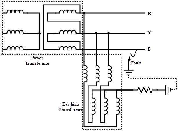
Grounding Transformers
These are used to create a ground path for delta connected or ungrounded star or Wye connected systems. This transformer provides a low impedance path to the ground and hence the system is maintained at neutral or ground or zero potential. When a single line to ground fault occurs on an isolated or ungrounded system, there exists no return path for the fault current. Hence no current flows through the faulty line, but this causes to raise the voltage on the other two lines. This results to overstressing of the transformer insulation and on other components. Hence, a grounding transformer provides a path to ground to prevent this.
Most commonly these are of single winding transformers with zigzag configuration and in some cases these are incorporated with special star-delta configuration. The star connection of the primary is connected to the supply system and the delta connected secondary remains unloaded. For a grounding transformer, load on the secondary is short time i.e., in the event of fault, hence the power ratings of grounding transformer is lesser compared to power transformers. These are designed to carry the no load and if one of the lines becomes grounded it supplies the current to the load. Because of this, the grounding transformer size and cost are less compared with continuous duty power transformer. These are mostly used in electrical transmission, utilities and industrial systems.
Leakage Transformers
These are designed in such that they have large leakage inductance compared with other transformers by binding primary and secondary windings loosely. These are also called as stray-field transformers. Due to this loose coupling between the primary and secondary windings, it provides inherent current limitation which helps to prevent the overloads. Therefore, under all operating conditions or even short circuit of secondary, the input and output currents are low enough to prevent the thermal overload conditions. This type of transformers is mainly used as welding transformers in arc welding, in such cases the short circuit currents are produced if the electrode gets in touch with the job. But, due to the high leakage inductance these currents are limited. Other applications of these transformers include high voltage discharge lamps and extra-low voltage applications where frequent short circuit conditions are expected such as children toys and door bell installations.
Resonant Transformer
It is a high voltage transformer that consists of two high Q coils (primary and secondary) that are wounded on either same ferrite or air core with capacitors are connected across the windings. This combination of an inductor with capacitor makes two coupled LC circuits. In some cases only secondary consists of capacitor thereby acts as a resonant coil.
The primary is connected to the periodic alternating current source such as a sawtooth or square wave in such that every pulse produces sinusoidal oscillations in tuned secondary. Due to the resonance, a high voltage is generated across the secondary. Hence, these transformers are used to generate high AC voltages. These are also used in electronic ballasts to light up the fluorescent lamps. Other applications of these transformers are radio transmitters, super heterodyne radio receivers, ignition systems, etc.
Another form of resonant transformers is a constant voltage transformer. By arranging the ferro –resonant tank circuit in the secondary and by choosing proper magnetic properties of the core, transformer can produce the constant voltage in secondary for a varying input voltage across the primary. The capacitor connected in the secondary draws current from it and saturates the secondary flux. Due to this saturation of flux, constant output voltage is produced across the load or secondary terminals even for a large change of input voltage.
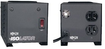
Isolating Transformer
Mainly for safety purposes, these transformers are used to isolate the equipment or load from the power source. It links the two circuits magnetically and separates them by not providing any conducting path between them. Any isolation transformer has turns ratio of unity that means these are about 1:1 transformers. These transformers provide the galvanic isolation such that the electric shock gets prevented. These are used in medical equipments so that any leakage of AC power into the devices connected to the patients prevented by this transformer. And also by using shielded type isolation transformers, coupling magnetic noise is prevented. In addition to the isolation and noise filtering, these are used as surge suppressors.
Instrument Transformer
Instrument transformers are used to protect or isolate the metering equipment, relays, instruments, and other control devices from the circuit which is operating at high voltage and currents and in which electrical quantities are to be measured. These are specially designed for the use of electrical instruments such as ammeters, voltmeters, watt meters, protective relays, energy meters, etc. to increase their range of measurement. These serve as voltage and current level conversion equipments from a high voltage circuitry to the levels suitable for measurement. The classification of instrument transformers includes both voltage and current transformers
Current Transformers
These are used to step-down the current levels so that ammeters, current coils of other instruments and relays are need not be connected directly to the high power operating circuit. Hence, all these instruments are isolated from high power circuit. A current transformer consists of separate primary and secondary windings. The primary consists of one or a few turns of heavy wire wound on a laminated core. This winding is connected in series with one of the power lines. In some CT’s, line conductor or wire itself serves as primary which is passing through the core. The secondary winding consists of a large number of turns of a small size wire which is wounded on the core. This winding is connected to instruments or relays. The usual standard rating of secondary current of a CT is 5A. And the primary winding current is determined by the maximum value of the load current.

Potential Transformers
These transformers operate as similar to the standard power transformer, but only difference is that these are small capacity transformers. These are used to step-down the voltage levels in the high power circuit to levels suitable for measuring range. PT’s are connected parallel across the line in which electrical parameters to be measured or protective system is to be connected. The primary or high voltage side winding is connected between one of the power lines to ground or between phase to phase lines. The secondary or low voltage side winding is connected to the load or potential coils of the various instruments and relays or other control equipments. Most commonly, the secondary winding is wounded for 115 or 120 volts.

Combined Instrument Transformer
This type of transformers can accommodate both current and voltage transformers in a single free standing unit. This type of transformers converts voltages and currents to the standardized low and measurable values which are useful for metering, protection and other high voltage control systems. This results to the optimum use of space and less supporting structures and mounting pads. These are mainly used in protective relaying and revenue metering applications.
Pulse Transformer
Pulse transformers are used to transmit the rectangular electric pulses of constant magnitude with fast rise and fall times from one circuit to the other by maintaining the isolation between them. These can be small signal, or medium sized power, or high voltage pulse transformers. In order to reduce the distortion of the rectangular pulse, these transformers must have low leakage inductance, high open circuit inductance and low tolerance for distributed capacitance. Signal type pulse transformers are smaller transformers that are used in telecommunication and digital logic circuits. Medium sized pulse transformers are power pulse transformers that are used in protection systems, power control circuits, camera flashes, etc. These transformers require low coupling capacitances to protect the primary side circuits against transients from the electrical loads. Large power pulse transformers are used in high frequency power converters to interface the low power control circuitry to the high voltage gate terminals of power semiconductors. These are also used in particle accelerators, radar systems, and other pulsed power applications.
RF Transformers
RF transformers are used in a variety of electronic circuits for several reasons such as impedance matching to transfer maximum power, DC isolation between the circuits, voltage and current step-up or step-down, interfacing between unbalanced and balanced circuits, etc. These transformers come as connector packages, surface mount packages and other different configurations. The steel laminations are not used for RF transformers. The working frequencies of this transformer are ranging from 30 KHz to 30 MHz and most often by the addition of capacitor to one winding helps to tune their windings for a particular frequency.
These can be air core, ferrite core, balun type transformers. Air core RF transformers used in printed circuit boards such that a few turns of a wire are soldered onto it. Ferrite core transformers are used in superheterodyne radio receivers which are mostly tuned type transformers. Balun transformers are used to connect the unbalanced and balanced circuits such as balanced amplifiers (common mode rejection applications).
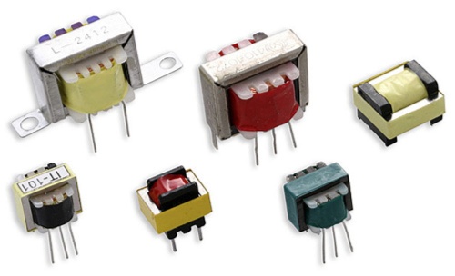
Audio Transformer
Audio transformers are specially designed transformers used to carry the audio signal in audio circuits. The working frequencies are ranging from 20 Hz to 20 KHz for this type of transformer. These are used for multi functionalities such as stepping up or stepping down the signal voltage, converting a circuit from balanced to unbalanced and vice-versa, decrease or increase of impedance of a circuit, blocking DC component of current and allowing AC signal, and to provide electrical galvanic isolation from one audio device to the other. These types of transformers include microphone input, line input, moving-coil phono input, line output, inter-stage and power output, microphone output, splitter, impedance conversion, direct box, Hum eliminators, loudspeaker toroidal AF transformers, etc.
Rotary Transformer
Many applications need electrical energy that has to be transferred to the rotating parts. In such cases these transformers is used. Most of the devices or machines that use slip rings and brushes are replaced with rotary transformers. Basically, these are similar to the conventional transformers, except they are arranged in such that both primary and secondary windings can be rotated. Most commonly, these are axial rotary and flat plane rotary transformers. The power transfer between primary and secondary is accomplished by electromagnetic induction through an air gap. This type of transformers has no wearing contacts, or contamination problems due to lubrication, noise, etc. These are most commonly used in grinding applications, torque sensors placed on electric motors, video cassette recorders, etc.

One Response
Please i need a power transformer manufactured by ALLTRONICS with the specification::
class 3 / ISC CL 15J (f) / p/n w 10 11 16 28
model wto 57 035r
output 33 vac (200 mA) 11 vac (1.6 mA) 3.3 vac (400 mA) 3.3 vac (400 mA) (4 points)
input : 120 vac 60 hz