Being a static device, a transformer could have the efficiency range as high as 98 to 99 percent. An ideal transformer is absolutely different from a practical transformer. Due to the presence of winding resistances, leakage flux and other losses, the performance of the practical transformer can be deviated from an ideal one.
All these effects are taken into account to evaluate the performance of a transformer either on load or no load. This article will helps one to know how the transformer behaves and its properties under load condition as well as no load condition.
Ideal Transformer on No Load
Transformers approach their ideal characteristics during the operation for which they are designed although no transformer is ideal. An ideal transformer has no primary and secondary winding resistance. The entire flux produced by the primary links with the secondary and hence no leakage flux.
Also, due to the infinite permeability of the core, it carries an infinite amount of magnetic flux without going into saturation. Eddy current and hysteresis losses of the core are neglected. When this ideal transformer operates on no load, the secondary current is zero (secondary terminals are open) as shown in figure below.
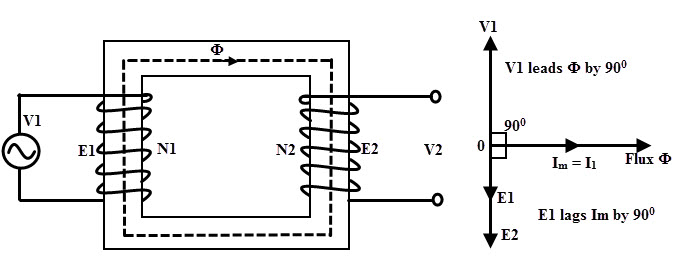 When the primary is excited with supply source with voltage V1, the primary winding draws a current I1 to produce the necessary flux in the core. This current is called magnetizing current Im. As the winding is purely inductive, the winding resistance is zero.
Due to this pure inductance, the magnetizing current Im lags the supply voltage V1 by 90 degrees. This current Im is very small and produce the alternating magnetic flux which is in phase with current Im as shown in figure.
This magnetic flux links with both primary and secondary windings and produce the EMFs E1 and E2 in respective windings. These induced EMFs oppose the supply voltage V1 (which is the cause for producing EMFs) according to the Lenz’s Law. Therefore, E1 is equal in magnitude as V1 but anti phase with V1.
Similarly E2 is anti phase with V1 but its magnitude depends on the number of turns in secondary, i.e N2. Hence, both EMFs E1 and E2 out of phase with V1 and are in phase with each other as shown in figure. The power input to the transformer is the multiplication of primary voltage and current and cosine angle between them.
Here the phase angle between primary voltage and primary current (or magnetizing current) is 90 degrees. The cosine 90 is zero, so the power input is zero. This is because under no load, secondary or output power is zero and also due to ideal one, losses also zero. Hence the input power of an ideal transformer under no load is zero.
Ideal Transformer on Load
Consider that the ideal transformer is loaded and the nature of the load is inductive so the output or secondary current lags by the output or secondary terminal voltage V2 by an angle Φ as shown in figure. This secondary current I2 produces the secondary flux which opposes the main flux in the core. So the mmf N2I2 is called demagnetizing ampere-turns.
To reduce the effect of secondary flux on the main flux, primary draws extra current I1’. This current is called a load component of the current. The ampere-turns N1I1’ balances N2I2 ampere-turns so that the net flux remains same. Hence the current I1’ is opposite in direction with I2 and its magnitude is determined by I1’ = N2/N1 × I2.
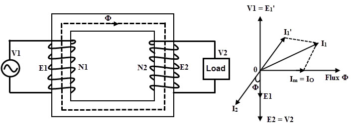
Now the primary current consists of both magnetizing current to produce the magnetic flux and the load component of current I1’. Hence I1 = Im + I1’. Comparing the above phasor with ideal transformer with no load, the primary current only makes the difference between them.
Due to the zero resistance drop, the EMF induced in the secondary E2 is equal to the V2 and are in the same direction as shown in figure.
Practical Transformer on No Load
A practical transformer differs from the ideal one due to various reasons like finite permeability of the core, finite windings resistance and leakage flux in both windings, etc. When the core is subjected to the alternating magnetic flux, eddy current and hysteresis losses takes place in the core.
These are called as iron or core losses. The primary winding of the practical transformer has certain resistance and hence small primary copper losses are also present. Therefore, when the practical transformer is operating, it takes the primary current to supply both core and winding losses.
Thus the no load current consists of two components. The first component is magnetizing component Im which is responsible for producing the necessary flux in the core. Another component is the active or core loss component Ic which supplies the total losses in the core. So the primary current
Io = Im + Ic
Due the winding resistance in the practical transformer, the no load current Io is no longer lags by the voltage at angle 90 degrees. Thus, Io lags by the voltage V1 by an angle Φo thereby no load power factor exist as shown in figure.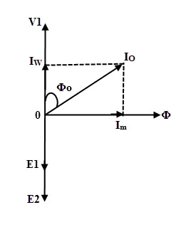 From the above phasor diagram,
The magnetizing component of no load current, Im = Io sin Φo
The core loss component of no load current, Ic = Io cos Φo
The no load current magnitude, Io = √ (I2m + I2c)
Where Φo no load angle between primary voltage and current.
Total power input on no load, Wo = V1× Io × cos Φo
It is to be noted that for a well designed transformer, the no load current in primary is about 3 to 5 percent of the rated or full load current. Due to the small winding resistance, copper losses are negligibly small. Thus the power input to the practical transformer operating on no load represents the iron losses in the transformer and are constant during all load conditions.
Wo = V1× Io × cos Φo = Iron losses
Transformer with No-load Example
Suppose the transformer is connected to 400 V, 50 Hz source supply operating with no load current of transformer of 5A at a power factor of 0.3 lagging. For this, we calculate the magnetising component of the no load current and iron losses.
From the above data, Φo = cos -1(0.3)
= 72.54 degrees
Therefore, Im = Io sin Φo
= 5 × sin 72.54
= 0.953 A
Iron losses, Pi = V1× Io × cos Φo
= 400 × 5 × 0.3
= 600 Watts
Transformer on Load (Without Winding Resistance and Leakage Reactance)
The moment when the load is connected to the transformer, the secondary current starts flowing through load. Depends on the load connected at the secondary, the magnitude and phase of the secondary current I2 are varied.
In case of resistive load, I2 is in phase with V2, if it is inductive I2 lags V2 and for capacitive load I2 leads V2. Due to the secondary mmf N2I2, secondary current I2 set up the magnetic flux Φ2 in the core.
This secondary flux opposes the main flux which is produced by the magnetizing component. This mmf is called demagnetizing ampere turns. Due to this opposition of flux, the EMF induced in the primary E1 reduces.
The primary draws more current from the supply due to the increase vector difference V1 – E1. This additional current drawing is due to the load and hence called as load component of the primary current I2’.
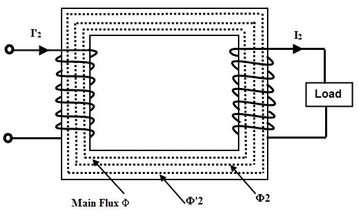
This load component current is anti phase with I2 and produces the flux Φ2’ in order to neutralize the effect of Φ2. Hence the mmf N1I2’ balances the mmf N2I2. Thus, the net flux in the transformer is constant that’s how the transformer is also called as a constant flux machine.
From above discussion,
N1I2’ = N2I2
I2’ = (N2/N1)I2
I2’ = K I2
Thus the primary current I1 of transformer under load has two components. The first one is no load current Io, which has both magnetising component Im and core loss component Ic.
This primary current lags by the supply voltage by an angle of Φo. Other current is the load component of current I2’, which is anti phase with secondary current I2. The phase of this current is decided by the nature of load connected.
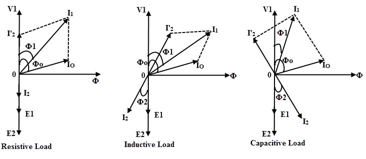
It may be noted that the above explanation described by neglecting various drops in the practical transformer such as resistance and leakage reactance drops. Thus, the E2 is same as V2. Above three figures show the phasor diagram for transformer which is operating with different loads.
The primary current I1 is the vector sum of currents Io and I2’. The secondary current I2 lags by V2 by an angle Φ2 for inductive load. In resistive load, I2 is in phase with E2 and in capacitive load, I2 leads the E2 by angle Φ2 as shown in figures.
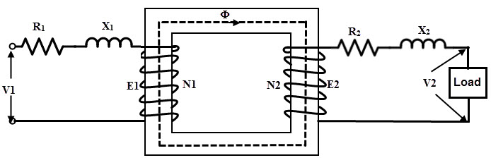
Transformer on Load (With Winding Resistance and Leakage Reactance)
The practical transformer windings possess certain resistance. These resistances of both primary and secondary windings not only cause the voltage drops I1 R1 and I2 R2 in respective windings but also ohmic losses I12 R1 and I22 R2.
When the current flows through the primary I1, the winding resistance causes a voltage drop I1R1 and due to this the EMF induced in the primary no longer equal to the supply voltage V1.
Therefore, E1 = V1 – I1R1
Similarly, the EMF induced in the secondary will not appear across the load terminals due to the I2R2 drop in the secondary winding.
Therefore, V2 = E2 – I2R2
In the above two equations, the subtraction should be performed vectorially. These drops are purely resistive and hence these are in phase respective currents.
Also, in practical transformer, in addition to the mutual or useful flux that links both primary and secondary windings, a small portion of the flux that completes the path through the air and links with respective windings alone is called as leakage flux.
The primary leakage flux is produced by the current I1 and links only with primary winding. And the secondary leakage flux is produced by the current I2 and links only with secondary winding. These leakage fluxes cause self induced EMFs E2 and E2 in their respective windings.
Hence, to produce E1 in the primary, the supply voltage has to overcome the self induced EMF in the primary. Similarly to produce the secondary terminal voltage V2, the induced EMF E2 has to overcome the secondary self induced EMF due to the leakage flux.
These EMFs are considered as voltage drops or reactance drops across fictitious reactances connected in series with windings. Thus I1X1 is the primary reactance drop and I2X2 is the secondary reactance drop.
Then, the basic voltage equations of the transformer becomes,
E 1 = V1 – I1 R1 – jI1 X1
V2 = E 2 – I2 R2 – jI2 X2
Thus by considering the effects of leakage reactance and winding resistance, a transformer can be visualised as below figure.
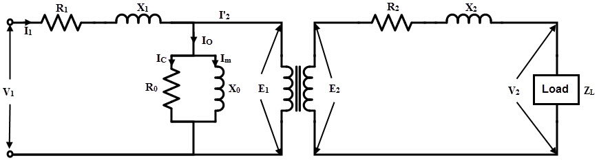
Also, no load current carried by the primary current in the transformer is required to maintain the mutual flux in the core as well as to respond to the core losses. With the no load equivalent, the practical transformer on load is shown in below figure. This is also called as an equivalent circuit of the transformer.
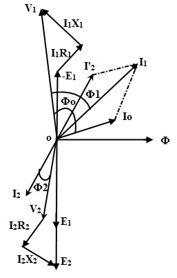
The below figure shows the phasor diagram of the transformer which is operating with a load. The secondary current I2 lags the voltage across the load V2 by an angle Φ2 so the power factor of the load is cos Φ2. ‘
The drop I2 R2 on the secondary side is in phase with secondary current, whereas I2 X2 drop leads by 90 degrees with reference to the current I2. By adding these drops to V2, we get induced secondary EMF E2 as shown in figure.
I2’ is the current flowing in the primary corresponds to the secondary current I2. Io is the no load current which has both Im and Ic components. Hence the total current flowing in the primary is the phasor sum of I2’ and Io as shown in figure. –E1 is the induced EMF in the primary which is a head of flux by 90 degrees.
The primary winding resistance drop I1 R1 is in phase with I1 and leakage drop I1 X1 leads 90 degrees with reference to I1. Hence, by adding –E1 and drops I1 R1 and I1 X1 we get the voltage V1 as shown in phasor diagram.