Introduction
Temperature is the most widely sensed parameter of all physical parameters because of its significance on materials and processes at the molecular level. Temperature is a specific degree of hotness or coldness as referenced to a specific scale. Temperature is also defined as the amount of heat energy in a system or object. Heat energy is directly related to molecular energy: molecular energy is greater when the heat energy is higher.
Temperature sensors monitor the changes that take place in materials or objects as their temperature changes. Temperature Sensors can detect a change in physical quantity that corresponds to temperature change. The physical quantity can be anything like resistance or voltage. Electrical to thermal energy based sensors use the heating effect of a current through a conductor. Thermal to electrical energy based sensors will require a temperature difference to operate.
Types of Temperature Sensors
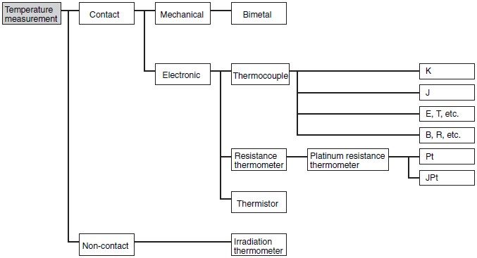
Temperature sensing can be of two types: contact based and non-contact based. In contact based temperature sensing, the sensor will be in physical contact with the object that is being sensed. In non-contact based temperature sensing, the sensor interprets the radiant energy of a heat source. The radiant energy is the form of energy emitted in the infrared portion of the electromagnetic spectrum. Non-reflective solids and liquids can be monitored using non-contact technique.
These two types of temperature sensors can be divided into three families: electromechanical, resistive and electronic.
Electromechanical Sensors
Bi-metal Thermostats or Bi-metallic Strips
Human bodies are so amazing that we either feel too cool or hot depending upon the weather condition. Our body has self-regulating mechanisms, which has the ability to adjust and maintain the body temperature at 370C. With the same idea, at our homes when we need to maintain the room temperature Thermostats are used.
Thermostat is contact type electro-mechanical sensor used to measure the temperature inside home. It was invented back in 17th century and now we have modern thermostat gadgets. Today a thermostat consists of heat activated switch and a temperature sensor. The switch will either open or close and causes the electrical circuit either to flow or to be interrupted. Thermostats can be electronic or mechanical type. Both types function are different but they measure temperature of the room.
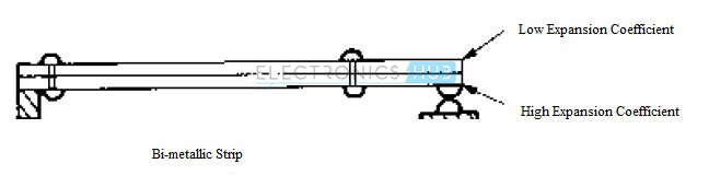
As the name implies, a bi-metal thermostat consists of two different metals riveted together to form a compound strip. The two metal strips are bonded together under heat and pressure. The thermal energy can be converted into electromechanical motion by employing different expansion rates or linear expansivity on two metals. Linear expansivity or expansion coefficient of a material is a fractional change of length per degree change of temperature. When heated, a strip will bend because one metal has a higher expansion coefficient that the other. This bend can be sensed by any displacement sensor.
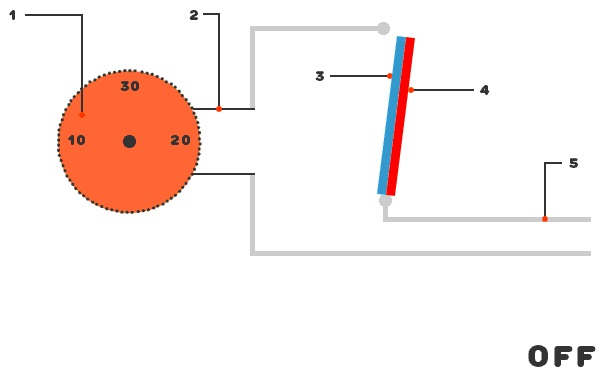
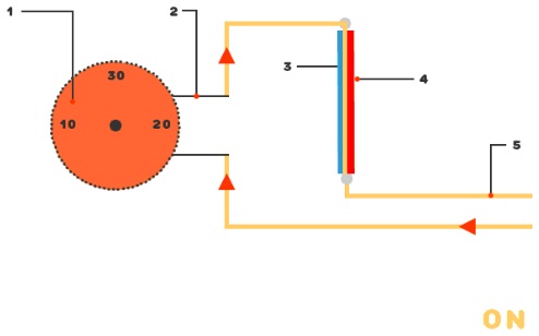
Working of a Thermostat
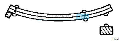
The basic principle of working is Thermal Expansion to switch an electrical circuit ON and OFF. It consists of two different metals like nickel, copper, tungsten or aluminum. Combination of any two metals forms a compound strip. They are bonded together using heat and pressure. This is called Bi-metallic strip. Two metals has different expansion rate. Therefore, when heat is applied on the strip, it undergoes a mechanical bending movement. Bi-metallic strip operates like a bridge, which helps to connect or disconnect the electric circuit of the heating or cooling system inside the house or industry.
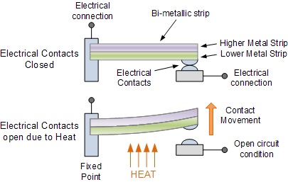
When the metals are in cold condition, the contacts are closed, which results in flow of current through the thermostat. During the application of heat, the bimetallic strip gets hot. This causes one metal to be hotter than the other does. The hotter strip expands more resulting in bending of the beam. This is turn makes the circuit to break and turns OFF the cooling or heating switch. The electrical contact is opened and current flow is stopped.
After sometime, the strip begins to cool. When it starts to cool, the metal that was expanded during heating will contract and tries to come back to its original size. The moment when it comes back to its original size, the circuit will be in contact and starts the cooling/heating process immediately.
1 – outer dial to adjust the temperature
2 – circuit to connect the dial with temperature sensor
3 – strip with 1st metal (brass)
4 – strip with 2nd metal (iron)
5 – inner electric circuit
2. Bulb and Capillary Thermostats: They use capillary action of expanding or contracting of a fluid to make or break electrical contact.
Resistive Sensors
Thermistors
What is a Thermistor?
Thermistors are thermally sensitive resistors. In thermistors, the electrical resistance changes according to their temperature. They are made of a combination of two or three metal oxides with zinc oxide among one of them. This combination is inserted in a ceramic base which is an insulator.
Thermistors are available in two types based on temperature coefficient: positive temperature coefficient thermistors and negative temperature coefficient thermistors.
In case of positive temperature coefficient thermistors, resistance and temperature are directly proportional to each other i.e. the resistance increases as the temperature rises.
Coming to negative temperature coefficient thermistors, resistance and temperature are inversely proportional to each other i.e. the resistance decreases as the temperature rises. Negative temperature coefficient thermistors provide a higher degree of sensitivity and are available in small configurations for rapid thermal response. NTC are made of ceramics and polymers. Materials like cobalt, nickel, iron and copper oxides are used.
Resistive Temperature Devices (RTD)
Similar to Thermistors the electrical resistance of resistive temperature devices changes to measure and control temperature. Resistive temperature devices consists sensing element, connecting wires and measuring instrument. The connecting wires are used between the sensing element and measuring instrument and a support is used for positioning the element in the process.
The sensing element is a resistor whose resistance changes with temperature. The sensing element consists of a coil of wire with conductors etched into it. This is housed in ceramic and sealed with ceramic glass. A conductive film can also be used instead of a coil of wire.
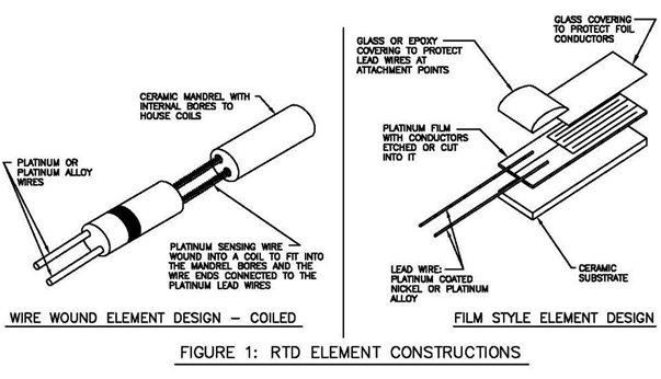
Image Resource Link: archives.sensorsmag.com/articles/0101/24/main.shtml
The sensing element should be positioned in such a way that it can reach the process temperature quickly. For applications where high vibration and shock are common, the wire wound device should be adequately secured. To measure resistance from a distance, extension wires between the sensing element and the instrument can be used.
Principle
It works on the principle that when temperature changes, the resistance of the metal also changes. An amount of electric current is passed through RTD element or resistor. The resistance of RTD element is measured using multimeter. The obtained resistance values are correlated to temperature. So, as the name implies when the temperature of the metal increases, the resistance of the metal increases. This results in increase of current.
RTD have positive temperature coefficient (PTC). Platinum material is used mostly for RTD construction. Therefore, Platinum Resistance Thermometer (PRT) also called, as Pt100 is the popular temperature sensor. This has a standard value of 100 ohm at 00C. Platinum is used due to the following reasons.
- Chemically inert
- Temperature and resistance are linear
- Has a larger temperature coefficient
- More stable
RTD Wire configurations
When RTD has more wires, it is said to be more accurate. There are two-wire and three-wire configurations system. Two-wire configuration is used only when approximate temperature value is required. The most commonly used configuration in industry is three-wire configuration. Generally, a Wheatstone bridge circuit is used as lead compensation technique as shown below.
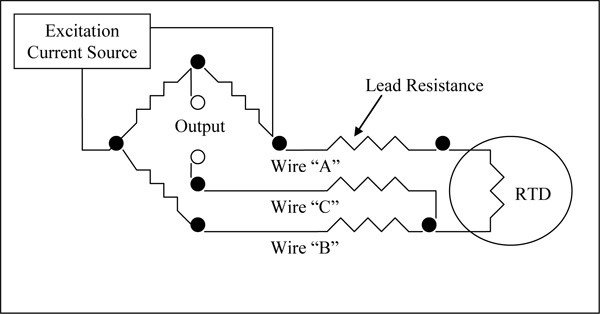
From the above figure, it is concluded that Wire A and B should be of same length. Impedances of wires A and B act on the opposite leg of the bridge and they cancel with each other. Due to this, wire C is allowed to carry a minimal amount of current. This is done with help of a a Wheatstone bridge.
Electronic Sensors
Thermocouples
When two conductors of dissimilar metals are joined at an end of a circuit, they form a thermocouple. They do not contain sensing elements like resistive temperature devices, so they are less limited in terms of materials used. They can handle much higher temperatures than resistive temperature devices.
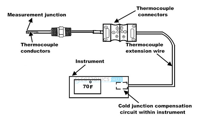
The build of a thermocouple consists of conductors and ceramic powder for insulation. Thermocouples have two junctions: hot junction and cold junction. The hot junction is measurement junction and the cold junction is reference junction. The measurement junction is exposed to process temperature and the other junction is maintained at a reference temperature.
When the junctions are subjected to different temperatures, a current that is proportional to their temperature difference, will flow in the wire.
Principles of a Thermocouple
It works based on three effects
- Seebeck Effect: When two dissimilar materials at different temperatures are connected together and heat is provided to any one of the metal, there will be flow of electron from hot metal to cold metal. This electron movement will result in generation of current in the circuit. The temperature difference between the metals will induce a potential difference between them.
- Peltier Effect: The reverse of Seebeck effect is the Peltier Effect. It states that when a potential difference is applied between two metals, it creates a temperature difference between the connected metals.
- Thomson’S Effect: Whenever two different metals are combined together, two junctions will be created. At this condition, due to temperature difference between two metals a voltage will be generated across the conductor.
Silicon Sensors
The electrical resistance properties of semiconductor materials are used in silicon sensors. The resistance properties are taken in bulk rather than just the junction of differently doped areas. At low temperatures, silicon sensors provide positive temperature coefficient i.e. linear increase in resistance with an increase in temperature.
Infrared Pyrometer (IR Pyrometer)
When the temperature is above absolute zero that is 00K, all the objects emit infrared energy. There is a direct correlation between the emitted IR energy and its temperature. Infrared sensors measure the IR energy emitted from an object and convert the reading to a voltage. The wavelength range of infrared is 4 to 20 microns. The output voltage is conditioned using a conditioning circuit to provide temperature reading. The factors that affect the accuracy of infrared sensing are reflectivity, transmissivity and emissivity. The measure of an object’s ability to reflect IR energy is its reflectivity. The measure of an object’s ability to transmit IR energy is its transmissivity. The measure of an object’s ability to radiate IR energy is its emissivity. An object is called a perfect reflector if its emissivity is 0.0. An object with an emissivity of 1.0 will emit or absorb 100% of the IR energy applied to it.
Additional Information
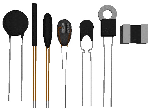
Thermistors
Thermistors are thermally sensitive resistors, generally formed using mixtures of metal oxides. The construction of thermistors is similar to that of carbon composition resistors. thermistors can take many physical forms like rods, plates, beads, miniature beads and also encapsulated in metal containers. Based on the type of mixture used in the construction, the thermistors have a positive temperature coefficient and negative temperature coefficient. Positive temperature coefficient thermistors are less common and are very non-linear. Negative temperature coefficient thermistors are most commonly used and follow the logarithmic law with no dramatic changes in resistance. If the resistance of a thermistor is known at a temperature θ2, then the resistance at temperature θ1 can be calculated using the following equation:
R1 = R2* e ((B/θ1) – (B/θ2))
Where
B is Thermistor constant
θ1 and θ2 are temperatures in Kelvin
R1 and R2 are resistances.
Negative Temperature Coefficient (NTC) thermistors are commonly used thermistors and are used for temperature control applications. Some of the applications are deep freezer thermostats, process controllers, low temperature oven controllers and room temperature sensors. The range of temperature for negative temperature coefficient thermistors is from -1500C to 2000C. Some negative temperature coefficient thermistors can withstand a temperature up to 6000C. The thermistor’s associated circuit will be a key factor in limiting the range of temperature. This is because the range of temperature is very less compared to the range of resistance.
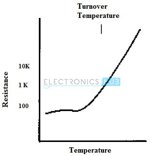
As the name indicates, a negative temperature coefficient thermistor will have a negative change of resistance to increase in temperature. The typical negative temperature coefficient thermistor characteristic is shown below.
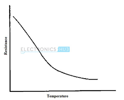
The shape of the curve is exponential rather than linear. In almost all the applications, the negative temperature coefficient thermistors have considerable advantages over the bimetallic strips.
A circuit employing negative temperature coefficient thermistor for temperature sensing is shown below.
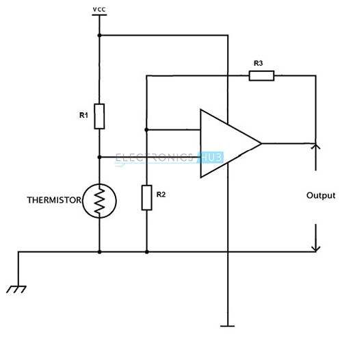
It makes use of an Op Amp and the sensitivity can be adjusted by changing the feedback ratio.
Semiconductor materials with temperature coefficients larger than the temperature coefficients of the resistor are used in the construction of negative temperature coefficient thermistors. The term NTC thermistor is used for the devices with large negative temperature coefficient. The term NTC resistor is used for the devices with small negative temperature coefficients.
Positive temperature coefficient thermistors are recent developments and are used in protection circuits for sensing temperature. Unlike negative temperature coefficient thermistors, the current voltage characteristics of positive temperature coefficient thermistors exhibit a change in direction.
The typical graph of resistance versus temperature or the characteristic curve of a positive temperature coefficient thermistor is shown below.
The direct usage of positive temperature coefficient thermistors is in very few applications because it is undesirable to have controlled current passing through the thermistor.
The construction of thermistors makes them the most sensitive of any temperature based sensors. Thermistors are inexpensive because they do not contain platinum. Thermistors are powered devices, i.e. they require external electrical input to function. Since thermistors are resistive devices, they generate heat in addition to the heat that is being measured. Depending on the construction, thermistors can be robust or fragile. Bead type thermistors have very thin lead wire that must be protected from vibrations and shocks.
The advantages of thermistors include low cost, fast response, small size and high resistance.
The disadvantages are self-heating, no resistance standards, requirement of additional circuitry to control application loads and low temperature exposure than thermocouples.
Thermocouple
Thermocouples are the most commonly used sensing elements in thermal sensors. A thermocouple consists of two conductors of dissimilar metals. The principle of a thermocouple is that these two metals always have a contact potential between them and this potential changes in temperature. To measure the contact potential, two connections or junctions in a circuit are required. These junctions are called hot junction or measurement junction and cold junction or reference junction. The hot or measurement junction is exposed to a process temperature and the cold or reference junction is maintained at a known reference temperature. When the junctions are at different temperatures, a current will flow in the wire that is proportional to the temperature difference and the voltage can be detected. Generally, the voltage will be in the order of a few milli volts. If the temperature at two junctions is same, the output voltage is zero. When the temperature at a junction is increased, the output voltage increases until it reaches a peak value. The characteristic curve of a thermocouple is shown below.
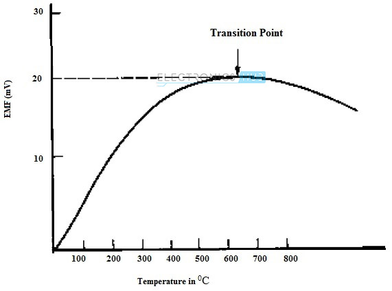
From the above characteristic curve it is clear that a thermocouple is useful only over a certain limited range of temperature. This is because of the non-linear shape of the curve and the reversal of the curve that takes place at temperatures that are higher that the transition point or turn over point.
The working of a thermocouple is based on three effects: Seebeck effect, Peltier effect and Thomson effect.
To calculate the EMF, thermocouples make use of Seebeck effect. According to Seebeck effect, the EMF in a thermocouple is given by the following equation.
E = a + bθ + cθ2
Where a, b and c are constants for the types of metals used in the thermocouple and θ is the temperature difference between them.
If the cold junction is maintained at 0 0C, the EMF is
E = αT2 + βT
Where α and β are the measured constants for the pair of metals and T is the difference in temperature.
When the temperature is below the transition point, the value of α is usually small and neglected. So the EMF is almost directly proportional to the difference in temperature.
According to Peltier effect, when two dissimilar metals are joined to form two junctions, an EMF is generated in the circuit due to the temperature difference between two junctions.
According to the Thomson effect, when two dissimilar metals are joined to form two junctions, a potential exists in the circuit due to the temperature gradient along the length of the conductor.
When a current flows through a conductor whose ends are maintained at different temperatures, certain amount of heat is released at a rate that is proportional to the product of the temperature gradient and the current.
The working of a thermocouple is explained below.
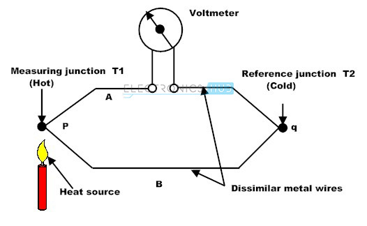
Two metals A and B are joined together to form two junctions, p and q. Junction p is the hot junction or measurement junction while the junction q is the cold junction or the reference junction. The temperatures at p and q are T1 and T2 respectively. If the temperatures of both the junctions are same, then equal and opposing EMF’s are generated at the junctions and the net current is zero.
But if the temperatures of the junctions are different, then an EMF is generated in the circuit that is a function of the difference in temperatures of the junctions.
Some of the common combinations of metals used in a thermocouple are Copper – Constantan, Iron – Constantan and Platinum – Rhodium. Copper – Constantan type thermocouples are generally used for lower range of temperatures. Platinum – Rhodium type thermocouples are mainly used for a higher range of temperatures.
Generally, an amplifier circuit is used to amplify the output voltages of thermocouple as they are very small. There is no need for an amplification circuit when the thermocouples are used together with a sensitive milli voltmeter for temperature measurement.
Of all sensor technologies, thermocouples have the widest range of temperatures. Depending on the type of the thermocouple, the temperature range can be from -200 0C to 2315 0C. Some of the most common thermocouple types are described below.
- Type S: It uses pure Platinum as one metal and an alloy of 90% Platinum, 10% Rhodium as other metal. This type of thermocouple is recommended for high temperatures and the range of temperature is 00C to 14000C and must be protected with a non-metallic tube with ceramic insulators.
- Type R: It uses pure Platinum as one metal and an alloy of 87% Platinum, 13% Rhodium as other metal. It is similar to Type S but Type R is used for industrial purpose and Type S is used for laboratory purpose.
- Type J: It is made up of iron as one metal and an alloy of Copper – Nickel as other metal. The temperature range is 00C to 8000C. They are suitable for vacuum or inert atmospheres. At higher temperatures, a heavy gauge wire is recommended as Iron oxidizes rapidly above 5400C and oxidizing atmospheres will reduce life.
- Type K: It uses alloys of Nickel – Chromium and Nickel – Aluminum. The temperature range of Type K thermocouple is 00C – 11000C. Since iron is not used as one of the metals, they are suitable for continuous oxidizing atmospheres mostly above 5400C. When exposed to Sulfur, type K thermocouple might be subject to failure. Between the temperature of 8160C to 10380C and at low oxygen concentrations, the preferential oxidation of Chromium causes green rot and a large negative calibration drift. To prevent this scenario, ventilation or sealing of protection tubes can be done.
- Type E: This type uses Nickel – Chromium and Copper – Nickel alloys as thermocouple. These types are recommended for continuous oxidizing atmospheres. They provide the highest thermo-electric output of all available thermocouples. The range of temperatures are 00C to 8000C.
- Type T: It uses Copper as one of the metals and an alloy of Copper – Nickel as other metal. Usable in vacuum, oxidizing, inert atmospheres and also works in subzero temperatures. The temperature range is -2000C to 4000C. It is resistant to corrosion in moist atmospheres.
The other commonly used types are Type B which is similar to Types R and S but with lower output and Type N which is used as a substitute to Type K where it has a shorter life and stability issues.
Because of the usage of different combination of materials, the thermocouples produce high output voltages at different temperatures and the output voltage curve is nearly linear. Hence the thermocouples are easy to interface with a controller.
There are three types of junction styles used in a thermocouple: grounded, ungrounded and exposed junctions.
In Grounded junction, in order to protect the hot or measurement junction, it is welded to the inside of a protective metal sheath. This might affect the thermal response, but makes it susceptible to electromagnetic interference.
In Ungrounded junction, a thermally conductive material is used to electrically insulate the hot junction from its protective metal sheath. This isolates the junction from electromagnetic interference, but increases thermal lag.
Exposed junction has the fastest response time. In this junction type, in order to form the hot junction, the sensing tip is made from two dissimilar wires joined by soldering, and welding.
The advantages of thermocouples are its small size, rapid temperature response, inexpensive, wider temperature range and durable to vibrations and shocks.
The disadvantages are its less stability at higher temperatures, requirement of extra protection from corrosions, the requirement of additional circuitry to control application loads and the use of special extension wires.
Resistance Thermometers
Resistance thermometers are also called as Resistance Temperature Detectors or Resistive Temperature Devices (RTD). Resistance Thermometers were formerly used only as laboratory devices. But the advances in the construction have led them to be used in many applications for which only thermocouples were once considered. These are used to measure the temperature by correlating the resistance of Resistance Thermometers with temperature.
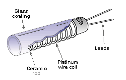
Image Resource Link: npl.co.uk/publications/good-practice-online-modules/temperature/types-of-thermometer/electrical-thermometers-resistance-thermometers/
Although several materials like Nickel, Copper can be used in the construction of a resistance thermometer, Platinum is preferred because of its considerable advantage of being the reference material for International Standards, used in the range -270 0C to 660 0C. Platinum also has the advantage of being resistant to corrosion, having almost linear resistance – temperature relationship over a wide range of temperatures and it can be prepared in a very pure state. Platinum is a very stable material in terms of both electrically and mechanically. So the drift of resistance values due to aging of the material is negligible.
Originally, Platinum – Resistance thermometer is a bulky piece of equipment, but miniature versions are available. Even though they are small, they combine the accuracy of the Platinum – Resistance principle with the ability of Platinum to withstand corrosive environments.
The sensing element in a Resistance thermometer is made of a length of fine coiled Platinum wire wrapped around a ceramic rod. The resistance of the wire varies with temperature and is measured by passing a current. The voltage is measured using a suitable bridge. A 2 wire or 3 wire or four wire arrangement is required when terminating the resistor in sensing element with extension wires. The value of the resistance of the external lead wire should also be taken into account. This is accomplished by connecting the lead wire to a Wheatstone bridge.
A simple 2 wire Wheatstone bridge circuit used for resistance thermometer is shown below.
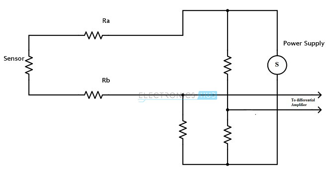
The resistances of the lead wires Ra and Rb are measured along with the resistance of the sensor.
Three wire arrangement is shown below.
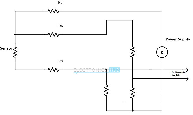
A two wire arrangement is not recommended because the longer the wire, the greater the lead resistance. The use of three wire arrangement will allow a good level of compensation of lead resistance by assuming all the lead resistances are identical. To achieve higher accuracy and lead wire compensation, a four wire arrangement is preferred.
For all the applications that use resistance thermometers, the current in the bridge must be low so that the self-heating of the Platinum wire is negligible. To operate the measuring bridges at low currents without compromising sensitivity, modern high impedance amplifiers are used.
Resistance thermometers are used in a variety of consumer applications like thermostats, refrigerators, ovens, automotive, air conditioning and instant water heaters.
Some of the popular industry applications are computers, printers, process control, motor temperature, power supplies, HVAC instruments and electronic assemblies.
Resistance thermometers are also used in medical applications like an incubator, respiratory and disposables.
The most common materials used in resistance thermometers are Platinum, Nickel, Copper and Nickel – Iron alloy.
The temperature limits of different materials are
- Platinum – 270 0C to 660 0C
- Nickel – 100 0C to 320 0C
- Copper – 75 0C to 150 0C
- Nickel – Iron – 0 0C to 200 0C
The wires used to connect the sensing element and measuring instrument are made of Nickel, alloys of Nickel, Silver plated Copper, tinned Copper and Nickel plated Copper. These wires are insulated with materials like PVC, Teflon and fiberglass.
The sensing element and the lead wires are inserted into a closed end steel tube which is packed with ceramic powder which acts as vibration damping or heat transfer material.
Since these are resistance devices, mass and self-heating of the device must be taken into account.
The advantages of resistance thermometers are resistance linearity, accuracy, repeatability, larger output voltages than thermocouples and wide range of temperature.
The disadvantages are higher cost and larger size than thermocouples, self-heating and less durable in high vibration environments.
Silicon Bandgap Temperature Sensor
Silicon bandgap temperature sensors are common form of temperature sensors used in electronic equipment. The principle of a Silicon bandgap temperature sensor is the temperature dependency of the forward voltage of Silicon diode. The forward voltage can be the Emitter – Base junction of a BJT.
VBE = VG0 (1 – T / T0) + VBE0 (T / T0) + (nKT / q) ln (T0 / T) + (KT / q) ln (IC / IC0)
Where
VG0 is bandgap voltage at absolute zero
T is temperature in K
T0 is reference temperature
VBE0 is bandgap voltage at T0 and current IC0
n is device constant
K is Boltzmann’s constant
q is charge on an electron
IC is collector current
The bandgap voltages at two junctions with the same temperature are compared at two different currents IC1, IC2 to eliminate the most of the variables in the above equation. The relationship can be formulated as
Δ VBE = (KT / q) ln (IC1 / IC2)
This voltage can be calibrated to calculate the temperature.
Silicon bandgap temperature sensors are available in an IC version with on chip signal conditioning. IC type Silicon bandgap temperature sensors have memory and can be accurately calibrated.
The applications of Silicon bandgap temperature sensors are engine coolants, air conditioning, overheating protection and power supplies.
The advantages of Silicon bandgap temperature sensors are less expensive than resistance thermometers, more linear than thermistors, higher output than thermocouples and resistance thermometers and IC level manufacturing.
The disadvantages of Silicon bandgap temperature sensors are less linear than resistance thermometers, limited temperature range, slower thermal response and larger package size.
