A Temperature Controlled System is a type of control system that automatically controls the temperature of an object or an area.
We commonly use temperature control systems in Air Conditioners, Refrigerators, geysers, etc. where the temperature is automatically adjusted as per the input settings. In order to implement a temperature control system, we need a temperature sensor, a controller, and a cooling system.
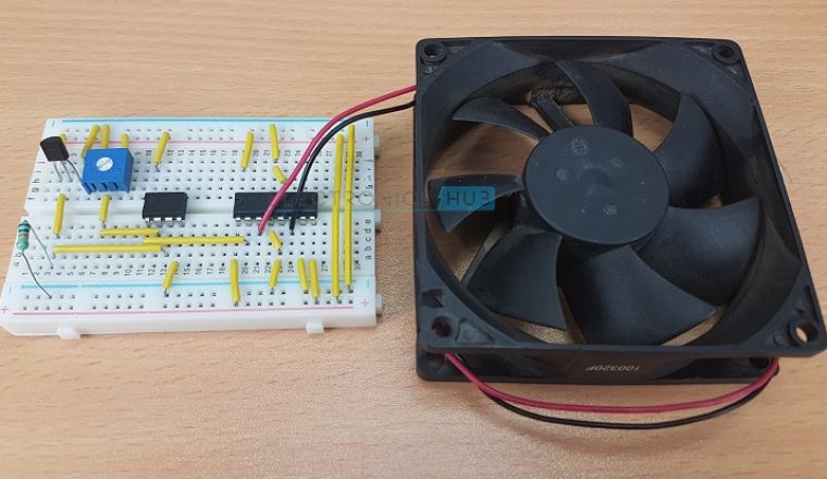
In this project, we have implemented a simple Temperature control system using simple components. The aim of this project is to automatically turn on or off the fan by detecting the surrounding temperature.
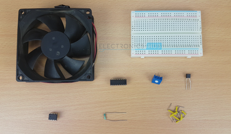
The hardware requirements for this simple temperature control system are: LM35, L293D, LM358, a fan and a few passive components (Resistors).
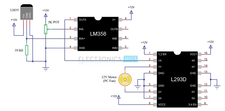
Temperature Controlled System Circuit Diagram
Required Components
- 1 x LM35 Temperature Sensor
- 1 x LM358 Op – Amp
- 1 x L293D Motor Driver IC
- 1 x 12V DC Fan
- 1 x 10 KΩ Resistor (1/4 Watt)
- 1 x 5 KΩ Potentiometer
- 1 x Breadboard
- Connecting Wires
- 12V Power Supply
Component Description
LM35 Temperature Sensor
LM35 is a Celsius scale temperature sensor device with its output directly proportional to the temperature. LM35 can measure temperatures in the range of -550C to +1500C.
In this project, we are using LM35 Temperature Sensor to measure the temperature of its surroundings and send the corresponding voltage values to the controller (Op – Amp).
LM358 Op – Amp
LM358 is an Operational Amplifier (Op – Amp) IC which consists of two independent Op – Amps. LM358 has a wide range of applications like filters, LED or Lamp Drivers, pulse generator, voltage controlled oscillator (VCO), amplifier, etc. In this project, we are using the LM358 Op – Amp IC in its comparator mode.
NOTE: Even though LM358 has two Op – Amps, we are going to use only one. Hence, other Op – Amp ICs like LM741 (Single Op – Amp) or LM324 (Quadruple Op – Amps) can also be used.
L293D Motor Driver IC: L293D is a Motor Driver IC which can drive two motors at a time with individual inputs as it has a dual H – Bridge Driver. In this project, we are going to drive a 12V PC Fan with this motor driver IC.
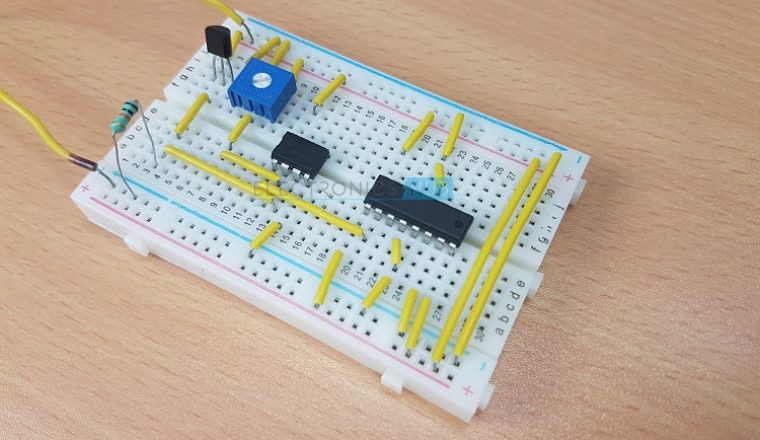
Circuit Design
LM35 has 3 pins: VCC, Data and GND. Connect the VCC and GND to 12V and GND respectively and form a voltage divider with data pin and a 10 KΩ Resistor. The output of the voltage divider is given to the non – inverting input (Pin 3) of the Op – Amp (LM358).
A 5 KΩ Potentiometer is connected to the inverting input (Pin 2) of the Op – Amp. Pins 8 and 4 are connected to 12V supply and GND. The output of the Op – Amp i.e. Pin 1 is connected to the 1A Pin (Pin 3), which is the first driver input of the Motor Driver IC L293D.
The second driver input of L293D (2A – Pin 7) is connected to GND. Pins 1, 8 and 16 (Enable 1, VCC2 and VCC2) are connected to 12V supply and Pins 4, 5, 12 and 13 are connected to GND. Motor (12V PC Fan) is connected between Pins 3 and 6 (1Y and 2Y).
Working of the Project
The working of the Temperature Control System project can be explained easily by comparing it with a closed loop control system.
A closed loop control system consists of an input, a control device, output and feedback. The input is typically a sensor that continuously monitors the test parameter. Here, the input is the LM35 Temperature Sensor and the parameter we are interested in measuring is the Temperature.
The data from the input is given to a control device or system. This control device will actuate the output according to the input signals. In our project, LM358 Op – Amp is controller and it acts as a comparator.
If the temperature is more than the desired temperature, we need to activate the fan.
So, we need to adjust the Potentiometer such that if the temperature increases above a value, the output from the Op – Amp should be HIGH.
This HIGH output from the Op – Amp is given to the Motor Driver, which along with the Fan, forms the output part of the Control System.
Since the other drive input of the motor driver is already connected to GND, whenever the output from the Op – Amp is HIGH, the Input to the L293D is HIGH and the Fan starts rotating.
This will cool down the surroundings and this phenomena acts as the feedback in the control system. If the temperature decreases, the LM35 senses it and signals the Op – Amp to turn off the Fan.
The following image shows the closed loop control system representation of the temperature control system.

Advantages
- The project implements a closed loop type control system for automatically adjusting the temperature.
- Closed loop type control system is more efficient than an open loop system as the output is continuously monitored as feedback.
Applications
- The Temperature Control System is a common type of control system implemented in different types of systems like Air Conditioning, Water Heaters, Refrigerators, etc.
- This type of Temperature Controlled Systems can also be implemented in industries, automobiles.

14 Responses
This project was tested?
Yes..
how can you set the temperature?
The lm35 is starting heating up when I put the source in the circuit, what should I do?
Hi, LM35 is rated for supply voltages up to 30V. If you are using a 9V battery or a 12V Supply, then there won’t be any problem. Try to check all the connections once again (like any short circuits).
How do you set the temperature and the threshold value above which the fan will switch on/off?
vary the potentiometer x
It is an automated circuit and it is used for kitchen purpose
Code required for the above project for lpc1768…?
“LM35 can measure temperatures in the range of – 550C to + 1500C.”
I’m pretty sure this is a typo, since lead melts at 327C, and absolute zero is -273C
It should say -55C to +150C
Yep. With the “degree” symbol.
We tried to this project ..but it’s not gtng started web connection is crct and connectd as shown
I assembled the circuit as shown. As soon as I give the power supply (9V), the fav starts rotating and won’t stop. I tried varying the 5k Pot but it has not effect on the speed of the fan.
How do we set the temperature of LM35 so that the fan starts rotating?
The fan starts rotating as soon as the power supply is connected. How to rectify this and how do we test this project?