Here we are going to see, how to control the speed of the small dc motor using 555 timer. Building projects using small permanent magnet dc motor for cars, robots, quads requires a speed controllers to make them work flawlessly.
In order to buy all those speed controllers for a high price, this tutorial will helps you to make your own speed controller at very less price.

Some Basics About 555 Timer
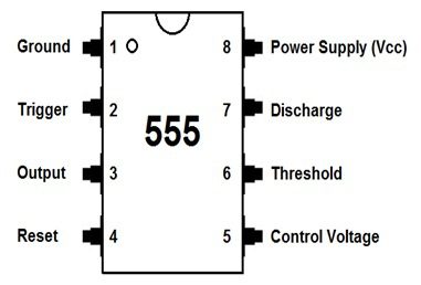
Basically, 555 timer is an 8-pin integrated chip which is capable of producing accurate time delays or oscillation. By connecting different values of resistor and capacitor to a 555 timer we can use it for counter less applications.
In simple, it has operating in 3 different modes
- Astable
- Monostable
- Bistable
Aim of our project is to control the speed of the dc motor using 555. To implement that we need to go with Astable mode of operation.
Astable state
“ here the output pulse is continuously switched between two states(high – low). “
Once we power up the circuit, there is no stable state in the output. Means, it will oscillate at a particular frequency depending upon the RC (resistor – capacitor) values connected with the 555 timer.
Either we can increase or decrease the frequency by changing RC values.
The basic astable connection for 555 timer was shown below
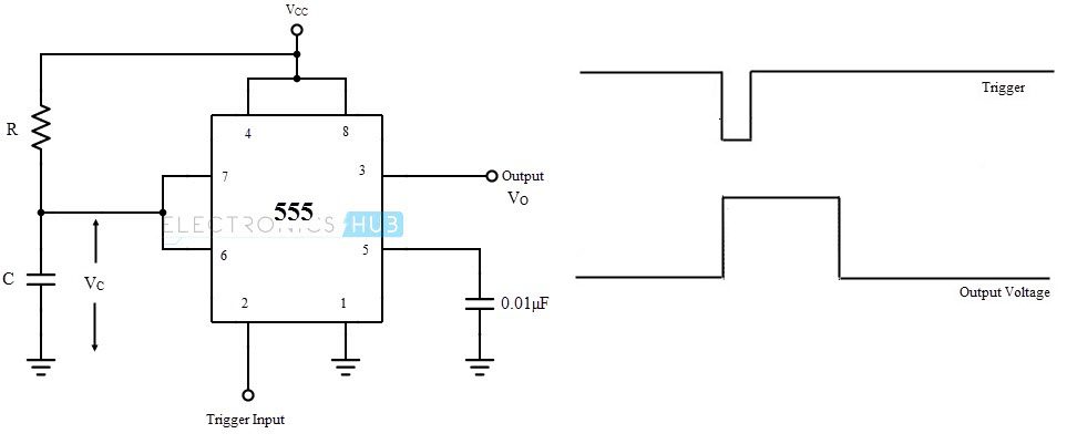
The below formula helps us to select the suitable values for RESISTOR and CAPACITOR for square wave generation.
NOTE : Resistor in ohms
Capacitor in farads
The formulas used are
ON time (secs) = 0.693 * (R1 + R2) * C
OFF time (secs) = 0.693 * R2 * C
Frequency = 1.44 / ((R1 + R2 + R2) * C)
Duty Cycle % = (ON / (ON + OFF)) * 100
Example
R1= 1K
R2= 330 ohms
C= 1000 uf
ON time (sec) = 0.693 * ((1×1000)+330) * (1000 X 10 e -6))
= 0.693 * 1330 * 0.001
= 0.92 seconds
OFF time (secs) = 0.693 * 330 * 0.001
= 0.22 seconds
frequency = 1.44 / ((1000 + 330 +330) * 0.001)
= 0.869 Hz
Duty Cycle % = (0.92 / (0.92 + 0.22)) * 100
= 80 %
Depending upon the Duty cycle the speed of the motor will vary
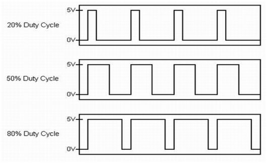
If duty cycle is more, then the speed of the motor will be high, if it is less , the speed of the motor will be low.
Circuit Diagram
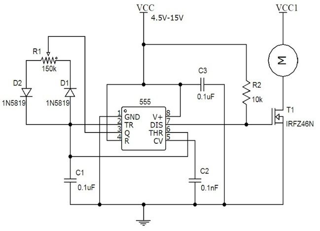 The above circuit diagram shows the speed controller using 555 with slight modification of our basic astable circuit.
Working
When we power up the circuit, consider that output is LOW. Thus capacitor c1 is discharging through D1 via R1.
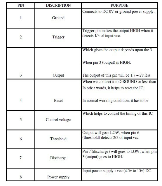
Once the capacitor charge is less than 1/3 voltage of Vcc,the TRIGGER (pin 2) will makes the OUTPUT (pin 3) to HIGH. Now the capacitor will charge via R2 through D2.
Once the capacitor’s charge is greater than 2/3 voltage of Vcc. The THRESHOLD (pin 6) will makes the OUTPUT to LOW. This process is continues.
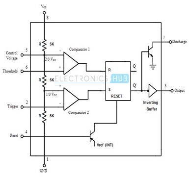
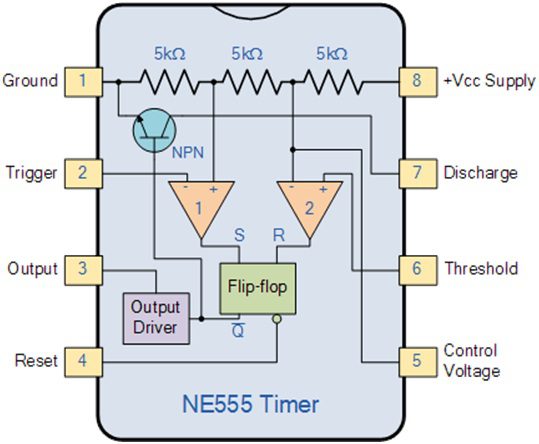
According to the internal connection of the 555, DISCHARGE (pin 6) is like an open collector in a transistor. When we provide the base current to the transistor the DISCHARGE pin will become LOW.
here the base current is provided by OUTPUT (pin 3) internally. This is the reason, when the output becomes HIGH correspondingly the DISCHARGE (pin 7) will become LOW.
In our circuit we connected a pull-up resistor to the DISCHARGE (pin 7).
When the DISCHARGE (pin 7) become LOW the current from the pull-up resistor will flow the ground and no current will flow to the gate of the MOSFET. Which makes the MOSFET to TURN OFF
If the DISCHARGE (pin 7) becomes OPEN then the current will flow to the gate of the MOSFET. Which makes the MOSFET to TURN ON
In our circuit diagram the left part of the pot acts as R1 and right part as R2 and the series capacitor as c1.
Instead of R1 and R2 we used a single pot called R1.
To find the output frequency,
frequency = 1.44 / (R1 * C1 )

2 Responses
But We can use simply variable rrgister for controlling the speed
show circuit connections plzzzzz