In this project, I will show you how to achieve Speed and Direction Control of DC Motor using Arduino UNO. It is a simple project using Arduino UNO and a few easily available components to control the speed of rotation of a DC Motor and also it direction of rotation.
Introduction
DC Motors are found everywhere: electronics, toys, fans, tools, discs, pumps etc. DC Motor is an actuator that converts the DC supply to rotation or movement.
There are different types of DC motors: Brushed DC motor, Brushless DC motor, Geared DC motor, Servo motor, Stepper motor and DC Linear Actuator.
Different types of motors are used in different applications like Robotics, precision positioning, industrial automation etc.
Generally, when a DC motor is associated with any microcontroller based system, it is often connected using a Motor Driver IC. A Motor Driver IC provides the necessary current for the motor to run. It can also control the direction of the rotation.
In this project, an Arduino based speed and direction control of DC motor without using Motor Driver IC is designed. A DC Motor can’t be connected to a Microcontroller as the output current of the Microcontroller is very small and it cannot drive the motor.
Hence, we use transistors to form an H-bridge to drive the motor. The circuit diagram, description and its working are mentioned below.
Circuit Diagram
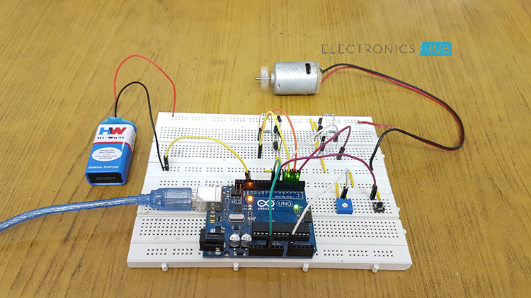
Components Required
- Arduino UNO [Buy Here]
- USB Cable
- Resistors (R1, R2, R3, R4) – 1KΩ
- Diodes (D1, D2, D3, D4) – 1N4007
- Transistors (Q1, Q2, Q3, Q4) – 2N2222
- DC Motor
- Push Button
- Potentiometer – 10KΩ
- Connecting Wires
- Breadboard
- 9V Battery
- Battery Connector
Component Description
Arduino Uno
It is a Microcontroller Based prototyping board. The microcontroller used on the Arduino Uno board is ATmega328p. Arduino is responsible for controlling the speed and direction of the motor with the help of other components.
2N2222
It is an NPN transistor with an output current of 800mA. The maximum output current that is available from Arduino’s I/O pins is 50mA, which is not sufficient to drive a motor. Hence, four transistors with high current capability are used.
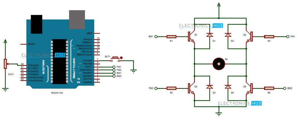
Circuit Design
Arduino is the main processing unit of the project. The wiper terminal of the POT is connected to the Analog Pin (A0) of the Arduino. The other terminals are connected to Vcc and GND. Four transistors are connected as shown in the circuit diagram.
With the load i.e. a DC Motor in the center, they form an H – bridge. Transistors Q1 and Q4 form the backward direction path while transistors Q2 and Q3 form forward rotation path.
The inputs to the transistors are given from the Arduino. The pins 3 and 2 of the Arduino are connected to the base of Q1 and Q4 respectively. Pins 5 and 4 are connected to base of Q2 and Q3 respectively. All these connections are made through four 1 KΩ resistors.
A DC Motor is an inductive load and can produce back EMF when we are changing the direction. In order to eliminate the effect of any back EMF, four diodes are connected across the collector and emitter of each transistor.
Working
The aim of this project is to control the speed and direction of a DC Motor without using a Motor Driver IC. Hence, we need to form an H-bridge using transistors in order to drive the motor. The working of the project is explained here assuming all the connections are made as per the circuit diagram.
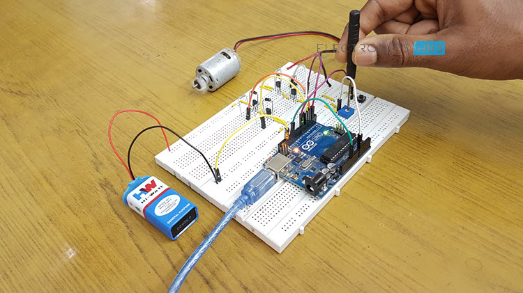
The POT is connected to the analog pin A0 of the Arduino. This is used to adjust the speed of the motor. The normal operation of the motor is to rotate in forward direction.
When a button, which is connected to the Pin 7 of the Arduino, is activated or pressed, the direction of the rotation is reversed and continue to rotate in that direction until the button is pressed once again.
For forward rotation of the motor, transistors Q2 and Q3 must be turned on. Hence, the outputs 5 and 4 of the Arduino are high.
The Arduino is programmed to detect a logic low on the Pin 7 when the button is pressed. When the button is pressed once, the transistors Q1 and Q4 must be turned on. Hence, the pins 3 and 2 of Arduino are made high. The motor rotates in reverse direction if the button is pressed once again.
NOTE: Instead of directly turning ON the transistors Q1 and Q3 whenever necessary, I am providing a PWM signal based on the value of the POT so that you can control the speed of rotation.
Code
Note
- The project is built using 2N2222 transistor, which has a maximum current rating of 800mA which is enough to drive low current motors. For driving motors with larger current requirements, BD139 (up to 1.5A) or other MOSFETS can be used.
Applications
- The circuit can be used to drive a single DC motor without Motor Driver IC.
- The circuit can be extended to 2 motors by implementing dual H-bridge connections.
- Can be used in simple robotic applications to control direction and speed of single motor.
Recommended Readings:

17 Responses
speed and driction control of dc motor using ardino in mini project given supply details tell me pls sir
We have provided all the details in the article…Please let us know clearly what more details you require..so that we can update it…
Can u submit code that lets dc motor to spin clockwise for 5seconds when button is pushed once and if it’s pushed second time it spins motor counterclockwise for 5seconds? Thank you a lot
You are talking about Sequential timer for DC motor or any motor.
Nice I search for this circuit only ty bro
i want a block diagram of this project please
Will it not damage the arduino board if i supply the motor with 12V?
The POT will also be connected to the 12V supply (according to the circuit).
From what i know the AO of arduino should have a max voltage of 5V.
The circuit shown in the circuit diagram is H bridge circuit.This circuit drives the motor. Arduino pins are used to give inputs to this circuit.So there will be no affect on arduino pins.
i am trying to build a refrigerator controller using ardinho board. as atest piece. what are the difficulties?
Hi can you send to us the codes that can we use to set the speed of dc motor and its rotation
Hi,Please go through the article.Code is Present in the article..
can i operate 24volt Bldc via this circuit, then which transistor should i use?
and which POT have i to use?
Costomer needs for the project
I want the Arduino code of this project.Please provide that it would be helpful.
WIll you be able to put the motor in forward and reverse as well as stopping it completely with this configuration.
I brought the components of the circuit explained above and uploaded the Arduino code above and in every time gave me error when I focused in the connection diagram I found a wire from 5 volt pin connected directly to about pin 8 what can I do sir?
Hi,
There is no connection for Pin 8. It is not used in the circuit.
Check your connections and try again. Make sure you connections and code match.