A Relay is a type of actuator that provides connection between two terminals or points in association with a control signal. In simple terms, a Relay is an electrical switch in which a small electrical current is required to control the switching operation (ON and OFF).
This is in contrast to normal switches, where the switching is done manually. There are two types of relays depending on the principle of operation: Electromechanical Relays and Solid-State Relays.
Electromechanical Relay uses an electromagnet to achieve the mechanical action of the switch. A small current given to the coil wound on an iron core will energize the coil and the contacts of the relay move to on position. When the coil is de-energized, the contacts move back to off position.
In contrast to electromechanical relays, which consists of moving parts and magnetic flux, a Solid State Relay or SSR doesn’t consist of any moving parts.
A Solid State Relay consists of semiconductor devices like transistors, thyristors, SCR’s or TRIACS to achieve the switching operation. Solid State Relays have many advantages over electromechanical relays.
One of the main advantage of Solid State Relays over electromechanical relays is that there are no moving parts and there is no scope of wear and tear problem.
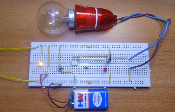
In this project, we designed a simple DIY solid state relay using an optocoupler and a TRIAC. This can be used in place of mechanical relays for current up to 4A (or depending on the TRIAC used).
Caution: Using breadboards with AC supply is dangerous. You need to be very careful. Make the circuit on a PCB”.
How To Make Solid State Relay?
Circuit Diagram
Components Required
- MOC3021 Optocoupler – 1
- BT136 TRIAC – 1
- 100Ω Resistor (½ W) – 1
- 100Ω Resistor – 1
- 330Ω Resistor – 2
- LEDs – 2
- Push Button – 1
Component Description
MOC3021
It is a 6 pin Optocoupler IC which consists of an Infrared emitting diode optically coupled to a photo TRIAC. Some of the main applications of this IC are solenoids or control valves, solid state relays, motor control, incandescent lamp dimmer, AC power switch etc.
It can be used for 115V and 240V AC applications. Pins 1 and 2 of the IC ARE THE Anode and Cathode of the diode while Pins 6 and 4 are the main terminals.
BT136
It is the TRIAC IC used in the project. This TRIAC can be generally used in applications where high bidirectional transient and blocking voltage is involved.
The maximum off-state voltage or blocking voltage is 600V and up to 4A of on-state RMS current can be allowed. The common applications are motor control, industrial lighting, heating applications and static switching.
Caution: Using breadboards with AC supply is dangerous. You need to be very careful. Make the circuit on a PCB”.
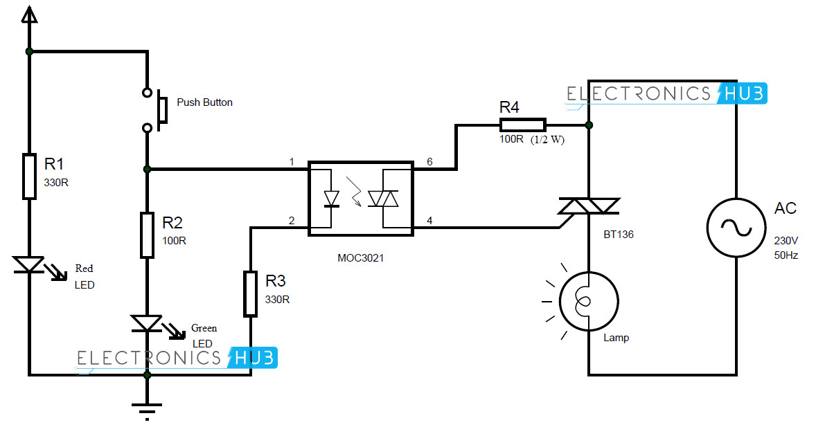
Circuit Design of Solid State Relay
A Red LED with a current limiting resistor is used as a power on indicator. A push button is connected between supply and Pin 1 of MOC3021.
A Green LED with current limiting resistor is connected from Pin 1. Pin 2 of MOC3021 is connected to ground through a current limiting resistor.
Pin 6 of MOC3021 is connected to T1 (Pin 1) of TRIAC BT136 with a 100Ω resistor. Pin 4 of MOC3021 IC is connected to gate (Pin 3) of the TRIAC.
T1 of TRIAC is connected to “hot” mains line. One end of the load like a lamp is connected to T2 of the TRIAC and other end is connected to “cold” mains line or ground.
Working of Solid State Relay
Relays are used in circuits where galvanic isolation is required i.e. when low power circuit is required to control a high current or high voltage circuit.
The best example is in case of microcontrollers that can control heavy loads like AC motors. The aim of this project is to demonstrate a DIY solid state relay. The working of the project is as follows.
As mentioned above, a small current at the input of the relay must be able to switch ON and OFF the relay contacts. Hence, a button is placed between the supply and the input (anode terminal of diode) of the MOC3021 optocoupler.
When the button is pushed, infrared emitting diode emits IR rays and is captured by the optically triggered TRIAC of optocoupler. The output of the optocoupler (internal TRIAC to be specific) is given to the Gate of the external TRIAC BT136.
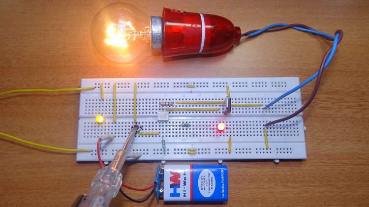
Hence, when ever the button is pushed, the external TRIAC is activated. As the terminals of the TRIAC BT136 are connected to mains supply, the load connected will be switched ON or OFF according to status of the button.
The function of a relay without any mechanical operations or moving parts is achieved as all the components are semiconductor devices. Hence, it is called a Solid State Relay.
A power on LED is used to indicate the circuit is powered on and a button status LED is also used to indicate switching operation.
Caution: Using breadboards with AC supply is dangerous. You need to be very careful. Make the circuit on a PCB”.
Here is the output video
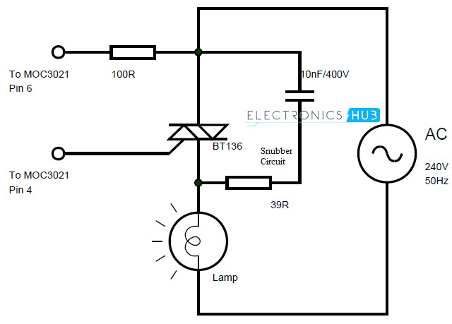
The circuit is suitable only for resistive loads. In order to use this for inductive loads, a snubber circuit must be placed between T1 and T2 of the TRIAC BT136.
A Snubber circuit is a series RC circuit used to suppress any spikes in voltage due to interruption in current. A 39Ω resistor in series with 10nF/400V capacitor can be used as the snubber circuit.
NOTE
- The TRIAC BT136 is connected to AC mains. Must be careful when dealing with AC.
- The circuit is a fully efficient relay in solid state form and can be used as a replacement to mechanical relays or expensive solid state relay ICs.
- As there are no moving parts, there is wearing out problem and the switching action is faster than mechanical relays.
- There will be no de-bouncing condition.
- Can be used with AC or DC loads.
Caution: Using breadboards with AC supply is dangerous. You need to be very careful. Make the circuit on a PCB”.

7 Responses
Dears sirs.
This is the excelent solutions in de the same circuits.
Thank your verey much for send this idea.
Luis
I get a very good idea about ur sending project of relay.thanks
it’s awesome sir,
Amazing.
Relays provide both NC and NO terminals. Is there a way of Implementing this circuit to achieve an NC path without using multiple optoisolators?
Super electronic s circuit bord like
What is Minimum DC Voltage Required Between pin 1 & 2. Can i use 5v DC at those pin for A Load of 100w Bulb Through Triac ??
This is a tutorial to control AC component using DC, but I want a circuit to control let’s say 12v DC component using 5v. Can you please help me out.