A servo motor is one of the widely used variable speed drives in industrial production and process automation and building technology worldwide.
Although servo motors are not a specific class of motor, they are intended and designed to use in motion control applications which require high accuracy positioning, quick reversing and exceptional performance.
These are widely used in robotics, radar systems, automated manufacturing systems, machine tools, computers, CNC machines, tracking systems, etc.
What are Servo Motors?
A servo motor is a linear or rotary actuator that provides fast precision position control for closed-loop position control applications. Unlike large industrial motors, a servo motor is not used for continuous energy conversion.
Servo motors have a high speed response due to low inertia and are designed with small diameter and long rotor length. Then how do servo motors work?
Servo motors work on servo mechanism that uses position feedback to control the speed and final position of the motor. Internally, a servo motor combines a motor, feedback circuit, controller and other electronic circuit.
It uses encoder or speed sensor to provide speed feedback and position. This feedback signal is compared with input command position (desired position of the motor corresponding to a load), and produces the error signal (if there exist a difference between them).
The error signal available at the output of error detector is not enough to drive the motor. So the error detector followed by a servo amplifier raises the voltage and power level of the error signal and then turns the shaft of the motor to desired position.
Types of Servo Motors
Basically, servo motors are classified into AC and DC servo motors depending upon the nature of supply used for its operation. Brushed permanent magnet DC servo motors are used for simple applications owing to their cost, efficiency and simplicity.
These are best suited for smaller applications. With the advancement of microprocessor and power transistor, AC servo motors are used more often due to their high accuracy control.
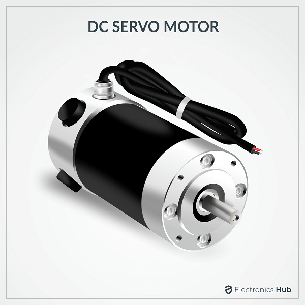
DC Servo Motors
A DC servo motor consists of a small DC motor, feedback potentiometer, gearbox, motor drive electronic circuit and electronic feedback control loop. It is more or less similar to the normal DC motor.
The stator of the motor consists of a cylindrical frame and the magnet is attached to the inside of the frame.
The rotor consists of brush and shaft. A commutator and a rotor metal supporting frame are attached to the outside of the shaft and the armature winding is coiled in the rotor metal supporting frame.
A brush is built with an armature coil that supplies the current to the commutator. At the back of the shaft, a detector is built into the rotor in order to detect the rotation speed.
With this construction, it is simple to design a controller using simple circuitry because the torque is proportional to the amount of current flow through the armature.
And also the instantaneous polarity of the control voltage decides the direction of torque developed by the motor. Types of DC servo motors include series motors, shunt control motor, split series motor, and permanent magnet shunt motor.
Working Principle of DC Servo Motor
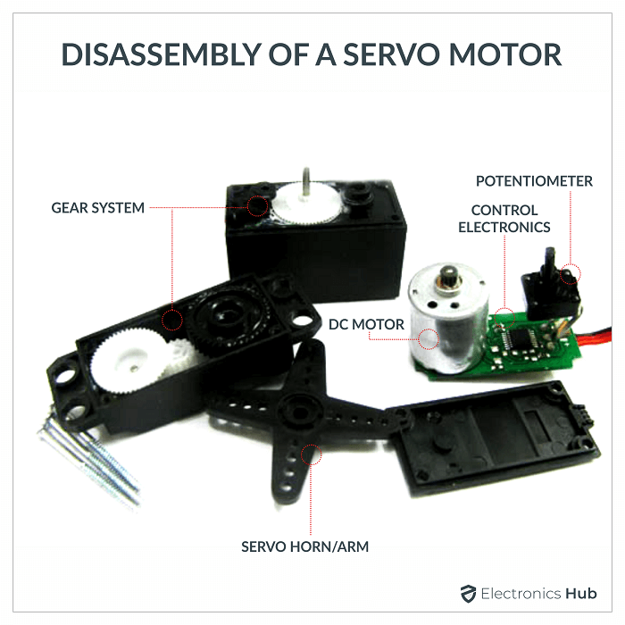
A DC servo motor is an assembly of four major components, namely a DC motor, a position sensing device, a gear assembly, and a control circuit. The below figure shows the parts that consisting in RC servo motors in which small DC motor is employed for driving the loads at precise speed and position.
A DC reference voltage is set to the value corresponding to the desired output. This voltage can be applied by using another potentiometer, control pulse width to voltage converter, or through timers depending on the control circuitry.
The dial on the potentiometer produces a corresponding voltage which is then applied as one of the inputs to error amplifier.
In some circuits, a control pulse is used to produce DC reference voltage corresponding to desired position or speed of the motor and it is applied to a pulse width to voltage converter.
In this converter, the capacitor starts charging at a constant rate when the pulse high. Then the charge on the capacitor is fed to the buffer amplifier when the pulse is low and this charge is further applied to the error amplifier.
So the length of the pulse decides the voltage applied at the error amplifier as a desired voltage to produce the desired speed or position.
In digital control, microprocessor or microcontroller are used for generating the PWM pluses in terms of duty cycles to produce more accurate control signals.
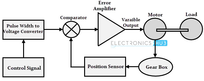
The feedback signal corresponding to the present position of the load is obtained by using a position sensor. This sensor is normally a potentiometer that produces the voltage corresponding to the absolute angle of the motor shaft through gear mechanism. Then the feedback voltage value is applied at the input of error amplifier (comparator).
The error amplifier is a negative feedback amplifier and it reduces the difference between its inputs. It compares the voltage related to current position of the motor (obtained by potentiometer) with desired voltage related to desired position of the motor (obtained by pulse width to voltage converter), and produces the error either a positive or negative voltage.
This error voltage is applied to the armature of the motor. If the error is more, the more output is applied to the motor armature.
As long as error exists, the amplifier amplifies the error voltage and correspondingly powers the armature. The motor rotates till the error becomes zero. If the error is negative, the armature voltage reverses and hence the armature rotates in the opposite direction.
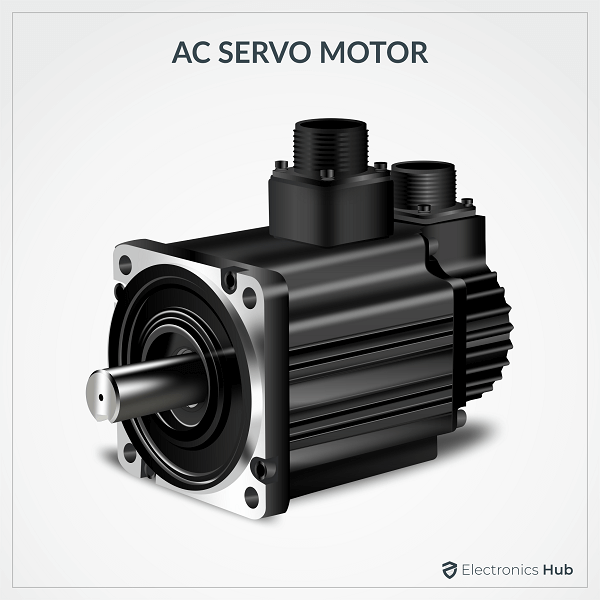
AC Servo Motors
AC servo motors are basically two-phase squirrel cage induction motors and are used for low power applications. Nowadays, three phase squirrel cage induction motors have been modified such that they can be used in high power servo systems.
The main difference between a standard split-phase induction motor and AC motor is that the squirrel cage rotor of a servo motor has made with thinner conducting bars, so that the motor resistance is higher.
Based on the construction there are two distinct types of AC servo motors, they are synchronous type AC servo motor and induction type AC servo motor.
Synchronous-type AC servo motor consist of stator and rotor. The stator consists of a cylindrical frame and stator core. The armature coil wound around the stator core and the coil end is connected to with a lead wire through which current is provided to the motor.
The rotor consists of a permanent magnet and hence they do not rely on AC induction type rotor that has current induced into it. And hence these are also called as brushless servo motors because of structural characteristics.
When the stator field is excited, the rotor follows the rotating magnetic field of the stator at the synchronous speed. If the stator field stops, the rotor also stops. With this permanent magnet rotor, no rotor current is needed and hence less heat is produced.
Also, these motors have high efficiency due to the absence of rotor current. In order to know the position of rotor with respect to stator, an encoder is placed on the rotor and it acts as a feedback to the motor controller.
The induction-type AC servo motor structure is identical with that of general motor. In this motor, stator consists of stator core, armature winding and lead wire, while rotor consists of shaft and the rotor core that built with a conductor as similar to squirrel cage rotor.
The working principle of this servo motor is similar to the normal induction motor. Again the controller must know the exact position of the rotor using encoder for precise speed and position control.
Working Principle of AC Servo Motor
The schematic diagram of servo system for AC two-phase induction motor is shown in the figure below. In this, the reference input at which the motor shaft has to maintain at a certain position is given to the rotor of synchro generator as mechanical input theta. This rotor is connected to the electrical input at rated voltage at a fixed frequency.
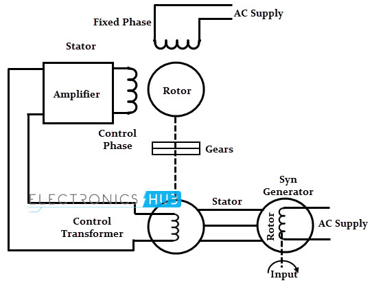
The three stator terminals of a synchro generator are connected correspondingly to the terminals of control transformer. The angular position of the two-phase motor is transmitted to the rotor of control transformer through gear train arrangement and it represents the control condition alpha.
Initially, there exist a difference between the synchro generator shaft position and control transformer shaft position. This error is reflected as the voltage across the control transformer. This error voltage is applied to the servo amplifier and then to the control phase of the motor.
With the control voltage, the rotor of the motor rotates in required direction till the error becomes zero. This is how the desired shaft position is ensured in AC servo motors.
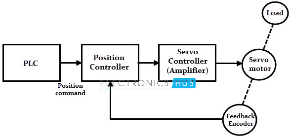
Alternatively, modern AC servo drives are embedded controllers like PLCs, microprocessors and microcontrollers to achieve variable frequency and variable voltage in order to drive the motor.
Mostly, pulse width modulation and Proportional-Integral-Derivative (PID) techniques are used to control the desired frequency and voltage. The block diagram of AC servo motor system using programmable logic controllers, position and servo controllers is given below.
Difference between the DC and AC Servo Motors
| It delivers high power output | Delivers low output of about 0.5 W to 100 W |
| It has more stability problems | It has less stable problems |
| It requires frequent maintenance due to the presence of commutator | It requires less maintenance due to the absence of commutator |
| It provides high efficiency | The efficiency of AC servo motor is less and is about 5 to 20% |
| The life of DC servo motor depends on the life on brush life | The life of AC servo motor depends on bearing life |
| It includes permanent magnet in its construction | The synchronous type AC servo motor uses permanent magnet while induction type doesn’t require it. |
| These motors are used for high power applications | These motors are used for low power applications |

8 Responses
super
I like your description of every chepter or every section of the description. I look everyday when I need only your description for reference of knowledge.
I feel AC and DC servo motor differernces are altered for some cases. Please correct.
MAGNET SERVO MOTOR: Type: T4C3BR0029
Magnet Servo Motor, DC Servo Motor
Thanks electronic hub ?❤
Thanks it was such a great information for me.
Very useful information for desigen makers