In this SCR tutorial, we will learn about some of the important SCR Ratings. These ratings include Voltage, Current, Power, Temperature, Turn ON Time, Turn OFF Time, etc.
Introduction
Under all operating conditions, the reliable operation of the SCR can be ensured only if it is operated such that its ratings are not exceeded. Each thyristor or SCR is manufactured to a particular current, voltage, power, temperature and switching frequency limits within which they can operate reliably.
These are called ratings, which can be minimum or maximum values that set limits on the capability of an SCR. Exceeding these limits even for short duration could considerably leads to malfunction or damage the SCR.
Therefore, for the benefit of users, the manufacturer gives a list of current, voltage, power, temperature ratings, etc. These ratings are essential for the correct application of SCR in various power electronic circuits. In practice SCRs with ratings higher than the required working ratings are selected to allow safety margin.

These ratings can be continuous, non-repetitive or surge and repetitive ratings. Depends on the unilateral or bilateral devices, continuous ratings are denoted in terms of RMS or average values. Surge and repetitive ratings are corresponding to peak values of the SCR.
So let us discuss various ratings of SCR in brief. Different voltage and current ratings are assigned with one or more subscripts for easy identification. The first subscript indicates the state of the SCR and includes
- F- Forward bias
- R- Reverse bias
- T- ON state
- D- Forward blocking state with gate open
The second subscript indicates the operating values and those are
- T- Trigger
- S- Surge or Non-repetitive value
- R- Repetitive value
- W- Working value
Voltage Ratings of SCR
The voltage capability of the SCR should not be exceeded during the operation even for short periods. So the SCR is assigned with different voltage ratings, which are the maximum voltages at which the SCR can function normally without breakdown of junctions. These are assigned in both blocking states of an SCR and can withstand against voltage transients. The various voltage ratings of an SCR are given below.
Peak Working Forward-blocking Voltage VDWM
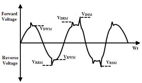
It specifies the maximum instantaneous value of forward blocking voltage across the SCR excluding all surge and repetitive transient voltages. Beyond this value of the voltage the SCR cannot withstand during its operation. This VDWM is equal to the maximum or peak value of the supply voltage wave shown in figure.
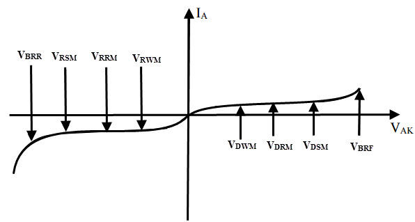
Peak Repetitive Forward-blocking Voltage VDRM
It is the maximum transient voltage that the SCR can block during it’s the forward blocking state repeatedly or periodically. This is specified with a specific biasing resistance between cathode and gate or at a maximum permissible junction temperature with gate circuit open.
This voltage VDRM is encountered or appeared across the SCR , when the SCR is turned OFF or commutated or due to diodes in the converter circuit. During the turn OFF process, an abrupt change in reverse recovery current causes to create a voltage spike , which is responsible of VDRM to appear across the SCR.
Peak Non-repetitive or Surge Forward-blocking Voltage VDSM
This is the maximum instantaneous value of forward surge voltage across the SCR that is of non-repetitive. This VDSM is less than the forward break over voltage VBO and this value is in the range about 130 percent of VDRM.
Peak Working Reverse Voltage VRWM
This is the maximum instantaneous value of reverse voltage across the SCR excluding all surge and repetitive transient voltages. This VRWM is equal to the maximum negative value of the supply voltage wave shown in figure.
Peak Repetitive Reverse Voltage VRRM
It is occurrence of the maximum reverse transient voltage repeatedly or periodically across the SCR in the reverse direction at permissible maximum junction temperature. Beyond this rating the SCR may get damaged due to excessive junction temperature. This voltage is also appeared due to the same reason as of VDRM.
Peak Non-repetitive or Surge Reverse Voltage VRSM
It refers to the maximum value of reverse transient voltage across the SCR that is of non-repetitive. This VRSM is less than the reverse break over voltage VBR and this value is in the range about 130 percent of VRRM. The surge voltage ratings VDSM and VRSM can be increased by connecting a diode of equal current rating in series with the SCR.
The above discussed voltage ratings are belonging to the forward and reverse blocking states with which the SCR is able to withstand with gate open.
ON-state Voltage VT
This is the voltage drop between the anode and cathode with specified junction temperature and ON-state forward current. Generally, this value is in the order of 1 to 1.5 Volts.
Gate Triggering Voltage VGT
This is the minimum voltage required by the gate to produce the gate trigger current.
Forward dv/dt Rating
This is the maximum rate of rise of anode voltage that will not trigger the SCR without any gate pulse or signal. If this value is more than the specified value, the SCR may be switched ON. The SCR in forward blocking mode is analogous to the capacitor with a dielectric.
So , the charging current flows through it when the applied voltage is increased. If the rate of rise of voltage is more, sufficient charges will flow through the junctions J2 of the SCR and hence the SCR will be turned ON without any gate signal.
This type of triggering is called as false triggering and in practice it is not employed. Also, this rating depends on the junction temperature. If the junction temperature is high, the dv/dt rating of the SCR is lower and vice-versa. With the use of snubber networks across the SCRs, it is possible to limit the maximum dv/dt applied to the SCR.
Voltage Safety Factor Vf
Generally, the operating voltage of the SCR is kept below the VRSM to avoid the damage to the SCR due to uncertain conditions. Therefore, the voltage safety factor relates the operating voltage and VRSM and is given as
Vf = VRSM / (RMS value of the input voltage * √2)
Current Ratings of SCR
Basically an SCR is a unilateral device and hence average current rating is assigned to it (while RMS current rating is assigned to bilateral devices). An SCR has low thermal capacity and short time constant. This means the junction temperature exceeds its rated value even for short over current.
This may lead to damage the SCR. Therefore, current ratings must be properly selected for long life of SCR , as the junction temperature depends on the current handled by it. Let us look at various current ratings of an SCR.
Average ON-state Current Rating ITAV
This is the maximum repetitive average value of forward current that can flow through the SCR such that the maximum temperature and RMS current limits are not exceeded. The forward voltage drop across the SCR is very low when it is in conduction mode. So the power loss in the thyristor is entirely depends on the forward current ITAV.
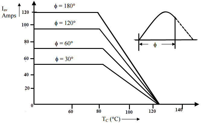
In case of phase controlled SCRs, average forward current depends on the firing angle. For the given average forward current, the RMS value of the current is increased with decrease in conduction angle. This leads to increase the voltage drop across the SCR which in turn increases the average power dissipation. Hence the junction temperature rises beyond the safe limit.
In order to limit the maximum junction temperature, the permissible average forward current has to be lowered with decrease in conduction angle. The manufacturers usually provide the data sheet that shows the forward average current variation with respect to the case temperature. As an example the current waveform formed from the positive half cycle for different conduction angles is shown in below.
RMS ON-state Current ITRMS
This is the maximum repetitive RMS current specified at a maximum junction temperature that can flow through the SCR. For a direct current, both RMS and average currents are same. However, this rating is important for SCRs subject to low duty waveforms with peak currents. And also this rating is required to prevent excessive heating in leads, metallic joints and interfaces of SCR.
Surge Current Rating ITSM
It specifies the maximum non-repetitive or surge current that the SCR can withstand for a limited number of times during its life span. The manufacturers specify the surge rating to accommodate the abnormal conditions of SCR due to short circuits and faults. If the peak amplitude and the number of cycles of the surge current are exceeded, the SCR may get damaged.
I2t Rating
This rating is used to determine the thermal energy absorption of the device. This rating is required in the choice of a fuse or other protective equipment employed for the SCR. This is the measure of the thermal energy that the SCR can absorb for a short period of time before clearing the fault by the fuse.
It is the time integral of the square of the maximum instantaneous current. For a reliable protection of SCR by the fuse or other protective equipment, the I2t rating of the fuse (or any other protective equipment) must be less than the I2t rating of the SCR.
di/dt Rating
It is the maximum allowable rate of rise of anode to cathode current without any damage or harm to an SCR. If the rate of rise of anode current is very rapid compared to the spreading velocity of the charge carriers, local hot spots are created due to concentration of carriers (on account of high current density) in the restricted area of the junctions.
This raises the junction temperature above the safe limit and hence the SCR may be damaged. Therefore, for all SCRs the maximum allowable di/dt rating specified in order to protect the SCR. It is specified in amperes/microseconds and typically it lies in the range 50 to 800 ampere/microseconds.
Latching Current IL
It is the minimum ON state current required to maintain the SCR in ON state after gate drive has been removed. After turning ON of the SCR, the anode current must be allowed to build up such that the latching current is attained before the gate pulse is removed. Otherwise the SCR will be turned OFF if the gate signal is removed.
Holding Current IH
This is the minimum value of the anode current below which SCR stops conducting and turns OFF. The holding current is associated with turn OFF process and usually it is a very small value in the range of mill amperes.
Gate Current IG
As the gate current is more, earlier will be the turn ON of the SCR and vice-versa. However, safety limits must be provided for gate by specifying maximum and minimum gate currents. For controlling the SCR, gate current is applied to the gate terminal. This gate current is divided into two types; minimum gate current IGmin and maximum gate current IGmax.
The minimum gate current IGmin is the current required by the gate terminal to turn ON the SCR where as IGmax is the maximum current that can be applied safely to the gate. Between these two limits the conduction angle of the SCR is controlled.
Temperature Rating of SCR
The forward and reverse blocking capability of the SCR is determined by junction temperature Tj. If the maximum junction temperature is exceeded, the SCR will be driven to conduction state even without any gate signal. This upper limit of Tj is imposed by considering the temperature dependence on break over voltage, thermal stability and turn OFF time.
And also an upper storage temperature limit Ts is also required to limit thermal stresses on silicon crystal, lead attachments and encapsulating epoxy. Excess of these two temperature limits may cause unreliable operation of an SCR. In some cases, upper storage temperature limit is higher than the operating temperature limit of an SCR.
Power Ratings of SCR
The power dissipation in the SCR produces a temperature rise in the junction regions. The dissipation of power in the SCR includes forward power dissipation; turn ON and OFF losses and gate power dissipation.
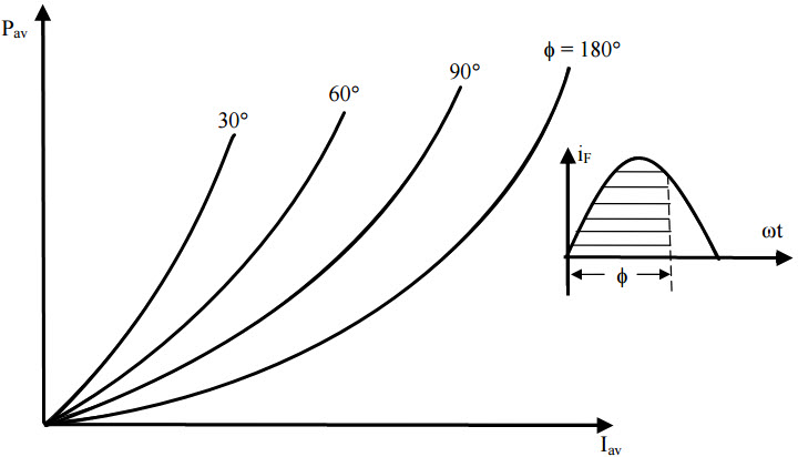
Average Power Dissipation Pav
It is the multiplication of the average anode current and forward voltage drop across the SCR. This is the major source of junction heating in an SCR for normal duty cycle operations. The peak power from a given source must not exceed the average power dissipation rating to maintain the safety of the device. This rating is specified for different conduction angles as a function of average forward current as shown in figure.
Gate Power Dissipation PG
This rating defines both forward or reverse peak power and the average power applied to the gate. If these ratings are exceeded, considerable damage occurs to the gate. Therefore, while calculating the voltage and currents applied, the width of gate pulses has to be considered (because the peak power is the function of time). For pulse type triggering, gate losses are negligible whereas gate signals with a high duty cycle, the gate losses becomes more significant.
Other power losses include ON state losses, OFF state losses, forward blocking losses and reverse blocking losses. Turn ON and OFF losses have to be taken into consideration while selecting the SCR rating since these constitute a significant portion of the total losses. And also forward and reverse blocking losses are very small compared to the conduction losses since a small leakage current and negligible voltage drop in blocking states.
Turn ON and Turn OFF Time Ratings
The turn ON time is the time interval between the instant at which the gate signal is applied and the instant at which the ON-state current reaches 90 percent of its final value. Shorter will be the turn ON time if the gate drive is increased. This turn ON time is valid only for resistive load because the rate of rise of anode current is slow in inductive load.
Therefore, the turn ON time does not indicate the time in which the device stays ON if the gate signal is removed. And if the load is resistive, turn ON time surely, indicates the time interval in which the SCR stays ON even the gate is removed.
Turn OFF time is the time interval between the instant at which the anode current goes zero or negative and the instant positive voltage is reapplied to the SCR. For fast switching SCRs both turn ON and OFF time values are very low.
