An RC oscillator is one of the sinusoidal oscillators and produces a sine wave output by using linear electronic components. The tuned LC oscillators operate well at higher frequencies, but at low frequencies, the capacitors and inductors in tank circuit or time circuit would be very large size.
Hence, RC oscillators are more suitable for low frequency applications. An RC oscillator consists of an amplifier and feedback network. This feedback network is a phase shift network made with number of capacitors and resistors which are arranged in a ladder fashion. That’s how this oscillator is also called as ladder type RC phase shift network.
The basic principle of the RC phase shift oscillator is that before feeding back a portion of the output of the amplifier to the input, the amplifier output passes through a phase shift network. The necessary condition for producing the oscillation is the total phase shift around the loop must be 360 degrees.
Hence, in addition to the 180 degrees phase shift introduced by the amplifier, this RC phase shift network gives 180 degrees phase shift and hence the total phase shift is 360 degrees which is also equal to zero degrees.
Let us discuss the RC phase shift circuit first which is used in feedback network before understanding the operation of this oscillator.
RC Phase Shift Network
The figure below shows a single RC network in which resistor R and capacitor C are arranged in series. In the figure, the total impedance of the circuit is a combination of resistance and inductive reactance, i.e.,
Z = R – j Xc
Z = Z ∠ – Ф Ohms
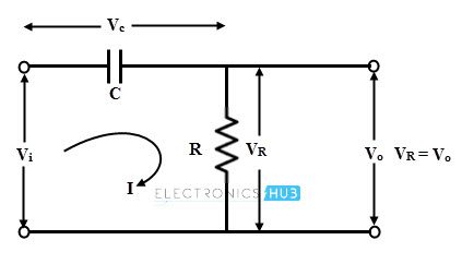
Consider that the value of the rms voltage applied is Vi volts. Then the current through the circuit is given as
I = (Vi ∠0)/ Z
I = (Vi ∠ Ф)/ Z
Where Z = √ (R2 + Xc2) and
Ф = tan-1(Xc / R)
From the above obtained equations, it is clear that the current leads the input voltage Vi by angle Ф. The drop across the resistor is in phase with current while the drop across the capacitor lags the current by 90 degrees and the resultant of these two voltage drops are shown in below figure.
Hence by adjusting the values of capacitor C and resistor R, the angle Ф is adjusted such that it is equal to 60 degrees.

Feedback Network
As mentioned above that multiple RC circuits are used in feedback network to provide the required phase shift. A total of 180 degrees phase shift must be provided by this network to make the overall phase shift around the loop 360 degrees.
A single RC section network provides a maximum of 90 degrees phase shift due to the existence of single pole in its transfer function. Therefore, a minimum of two RC networks are enough to produce required 180 degrees phase shift.
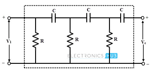
However, in a practical RC phase shift oscillator, three RC phase shift networks are cascaded with each section providing 60 degrees of phase displacement.
So the total phase shift obtained by these three sections in feedback network is 180 degrees (3 × 60). This feedback network is shown in figure below.
RC Oscillator Circuit
An RC phase shift oscillator consists of a common emitter single stage amplifier with a phase shift feedback network consisting of three identical RC sections. The single stage amplifier can be built with either transistor or operational amplifier (Op-amp) as an active element.
RC Phase Shift Oscillator Using BJT
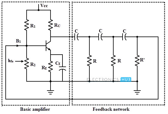
In this transistorized oscillator, a transistor is used as active element of the amplifier stage. The figure below shows the RC oscillator circuit with transistor as active element. The DC operating point in active region of the transistor is established by the resistors R1, R2, RC and RE and the supply voltage Vcc.
The capacitor CE is a bypass capacitor. The three RC sections are taken to be identical and the resistance in the last section is R’ = R – hie. The input resistance hie of the transistor is added to R’, thus the net resistance given by the circuit is R.
The biasing resistors R1 and R2 are larger and hence no effect on AC operation of the circuit. Also due to negligible impedance offered by the RE – CE combination, it is also no effect on AC operation.
When the power is given to the circuit, noise voltage (which is generated by the electrical components) start the oscillations in the circuit. A small base current at the transistor amplifier produces a current which is phase shifted by 180 degrees.
When this signal is feedback to the input of the amplifier, it will be again phase shifted by 180 degrees. If the loop gain is equal to unity then sustained oscillations will be produced.
By simplifying the circuit with equivalent AC circuit, we get
The frequency of oscillations,
f = 1/ (2 π R C √ ((4Rc / R) + 6))
If Rc/R << 1, then
f= 1/ (2 π R C √ 6)
The condition of sustained oscillations,
hfe (min) = (4 Rc/ R) + 23 + (29 R/Rc)
For a phase shift oscillator with R = Rc, hfe should be 56 for sustained oscillations.
From the above equations it is clear that, for changing the frequency of oscillations, R and C values have to be changed.
But for satisfying oscillating conditions, these values of the three sections must be changed simultaneously. So this is not possible in practice, therefore a phase shift oscillator is used as a fixed frequency oscillator for all practical purposes.
Example Problem
For a transistorized RC oscillator, select the value of capacitor C and transistor hfe in order to provide 2 KHz oscillator frequency with resistance Rc=10KOhms , R=8KOhms
Given that
Rc = 10 × 103Hz
R = 8 × 10³Hz
f = 2 × 10³Hz
In phase shift oscillator, the frequency of oscillations is given by
f = 1/ (2 π R C √ ((4Rc / R) + 6))
2 × 103= 1/ (2 π × 8 × 103 C √ ((4 × 10 × 103 / 8 × 10³) + 6))
C = 3.0 × 10⁻⁹ F or 0.003 µ F
The value of the transistor gain is given by
hfe ≥ (4 Rc/ R) + 23 + (29 R/Rc)
hfe ≥ (4 × 10 × 103/ 8 × 10³) + 23 + (29 × 8 × 103 / 10 × 103)
hfe ≥ 51.2
Hence the capacitor value is C = 3.0 × 10⁻⁹ F and hfe = 51.2.
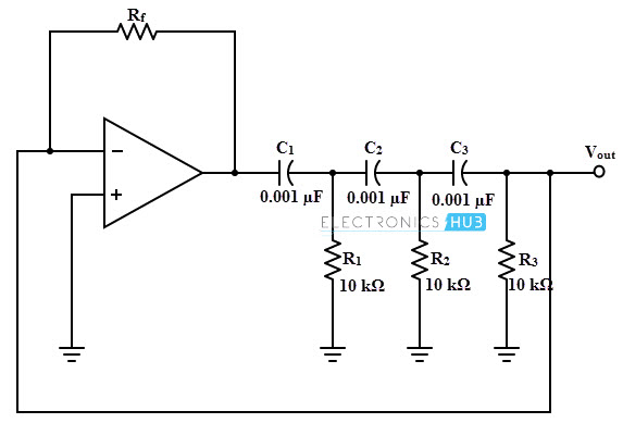
RC Phase Shift Oscillator Using Op-amp
Operational amplifier RC oscillators are commonly used oscillators , as compared to the transistorized oscillators. This type of oscillator consists of an op-amp as amplifier stage and three RC cascaded networks as feedback circuit as shown in figure below.
This op-amp is operated in inverting mode and hence the output signal of the op-amp is shifted by 180 degrees to the input signal appeared at inverting terminal. And an additional 180 degrees phase shift is provided by the RC feedback network and hence the condition for obtaining the oscillations.
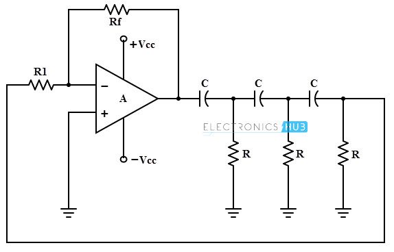
The gain of the amplifier or op-amp is adjusted with help of Rf and R1 resistances. To get the required oscillations, the gain is adjusted in such a way that the product of op-amp gain and gain of feedback network is slightly greater than 1.
The above circuit acts as an oscillator as the loop gain is greater than unity , if the op-amp provides the gain greater than 29.
The frequency of oscillations,
1/ (2 π R C √ 6)
The condition of oscillations is given by A ≥ 29.
We can get this gain value of the amplifier (A) so that the oscillations occur in the circuit by adjusting Rf and R1.
Example Problem
For a given op-amp RC phase shift oscillator, determine the value of Rf necessary for the circuit and also determine the frequency of oscillations.
 We know that the condition for oscillation is expressed as
A = 29
Where A is the again of the amplifier, hence the feedback network gain, β = 1/29 = R3/Rf.
Therefore, Rf = 29 × R3
= 29 × 10 × 103
= 290 K Ohms
Since the R1 = R2 = R3 = R and C1 = C2 = C3 = C,
Then the frequency of oscillations is
f = 1/ (2 π R C √ 6)
= 1/ (2 π × (10 × 103) × 0.01× 10-6 × √ 6)
= 6.5 KHz.
Advantages of Phase Shift Oscillators
- Due to the absence of expensive and bulky high-value inductors, circuit is simple to design and well suited for frequencies below 10 KHz.
- These can produce pure sinusoidal waveform since only one frequency can fulfill the Barkhausen phase shift requirement.
- It is fixed to one frequency.
Disadvantages of Phase Shift Oscillators
For a variable frequency usage, phase shift oscillators are not suited because the capacitor values will have to be varied. And also, for frequency change in every time requires gain adjustment for satisfying the condition of oscillations.
- These oscillators produce 5% of distortion level in the output.
- This oscillator gives only a small output due to smaller feedback
- These oscillator circuits require a high gain which is practically impossible.
- The frequency stability is poor due to the effect of temperature, aging, etc. of various circuit components.

3 Responses
Here we are using a BC107 transistor for implementing RC phase shift oscillator. BC107 is an audio frequency transistor which is made up of silicon.
What is the value of hfe for the oscillations in transistorized rc phase shift oscillator
Minimum hfe to be 44.5 ie 45 for a transistor for circuit to oscillate