According to Maxwell’s equations, electromagnetic fields are produced or created by the time varying sources such as currents and charges. If these fields are produced by the time varying sources and are confined to propagate as a wave inside a wave guide or along a transmission line, then the wave is generally referred as a guided wave.
What Is Radiation of Electromagnetic Waves?
A radiating system is formed when these sources, finite in size creates a wave which then propagates away from them (with no connection to the sources) in an unbounded medium. This process of collective formation of radiation is called as the radiation of electromagnetic waves.
The below figure shows the electromagnetic spectrum varies from a wavelengths of 10m to 0.1µm and their corresponding frequency ranges are indicated.
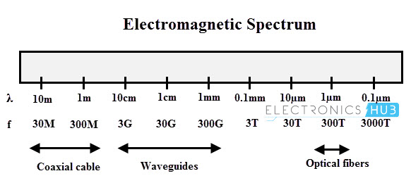
Depends on the frequency of operation and the wavelengths, these electromagnetic waves are carried through different medium such as coaxial cables, waveguides, optical fibers, etc. At larger bandwidth, we can transmit more information and hence the frequency of the waves generally increased to higher levels.
For low frequency applications (like in transmission and telephone lines), electromagnetic waves are transmitted through coaxial cables which has moderate losses and low electromagnetic interference.
But for very high applications, the center conductor of the coaxial cable has sufficient losses and hence the conducting surface area is reduced. To reduce this effect, waveguides are used which are basically hollow pipes inside which the electromagnetic waves propagates.
Hollow metal pipes, coaxial cables, and fiber optical cables are the examples of waveguides. And for transmitting or receiving of the electromagnetic energy in the form of radiation we generally use antennas.
Introduction to Waveguides
Any system of conductors and insulators which is used for conveying the electromagnetic wave is called as a wave guide. It is a hollow conducting medium or tube which transmits high frequency electromagnetic waves from source to destination.
A specially designed hollow metalloid pipes are used as wave guides. Such constructed wave guides provide an attenuation of transmission line to transmit the electrical energy at microwave frequencies. Inside a wave guide, any configuration of electrical and mechanical fields must have a solution of Maxwell’s field equations.
In addition, the boundary conditions imposed by the walls of the guides must have to be satisfied by these fields.
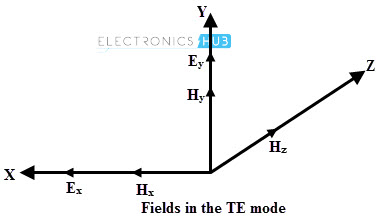
There are different modes by which field configurations meet the requirements. These modes include transverse electric or TE modes or H modes.
In such modes, electric field is transverse to the axis of the guide and has no component in the direction of the guide except at the location of the associated magnetic field.
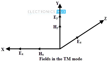
In another particular case, magnetic field is everywhere transverse to the guideline axis and some places the electric field has components in the direction of propagation. Such type of mode is called TM or transverse magnetic mode or E mode.
Classification of Waveguides
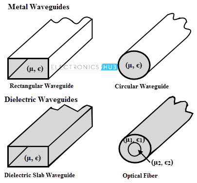
Generally waveguides are classified into two major types namely Metal waveguides and Dielectric waveguides.
Metal Waveguides
These waveguides are in the form of a closed metal pipe. By the reflection from the conducting walls, the wave propagation is characterized inside the metal wave guide.
These are used in microwave ovens, microwave radio links, satellite communication, radar sets, etc as a transmission line at microwave frequencies to connect microwave receivers and transmitters to their antennas.
Dielectric Waveguides
These waveguides consists of dielectrics only. To propagate the electromagnetic wave along the wave guide, it employs the reflection from dielectric interfaces.
Rather than having a hollow pipe, dielectric waveguide employs a solid dielectric rod. In practical, an optical fiber is a dielectric waveguide designed to work at the optical frequencies.
Again, these waveguides are classified into two types namely rectangular waveguide and circular waveguide.
In rectangular waveguide, electric field varies with time having maximum at the center whereas the magnetic lines are tangential to the walls.
Both of these are curved round and pass through the guide. The area of this waveguide is in rectangular fashion. These are used at the ultra high frequencies as alternate to transmission line for transmission of electrical energy.
Circular Waveguide has the uniform circular cross section along their length. These are used as an alternate to the rectangular waveguides. These are often used to feed the conical horns and the round cross section makes it easy to machine. These waveguides supports transverse magnetic (TM) and transverse electric (TE) modes.
Waveguide Propagation Modes
Consider a time varying source of electromagnetic radiation, the propagation of electromagnetic waves associated with both electric and magnetic fields through a medium characterized by permeability µ and permittivity є must satisfy the source-free Maxwell’s equations. And are given as
∇ × E ̅ = − jwµ H ̅
∇ × H ̅ = jw є E ̅
For obtaining the electric and magnetic fields, these Maxwell’s equations can be manipulated into wave equations as
∇2 E ̅ + K2 E ̅ = 0
∇2 H ̅ + K2 H ̅ = 0
Where K = w √µє which is a real value for lossless media and is a complex value for a lossy media.
The fields of a wave (electrical and magnetic) propagating in z-plane direction either in unguided (in case of plane wave) or guided (transmission or waveguide) wave propagation through an arbitrary medium with propagation constant ɣ are characterized by a z-dependence of e- ɣz.
These fields of a wave in rectangular coordinates can be written as
E ̅ (x, y, z) = e ̅ (x, y) e- ɣz
H ̅ (x, y, z) = h ̅ (x, y) e- ɣz
Where ɣ = α + j β and α is the wave attenuation constant and β is the wave phase constant. When the wave travels through the pure or loss less medium, then the propagation constant is purely imaginary whereas in case of lossy medium, it is a complex –valued.
The derivatives of the transverse fields with respect to z are
∂ E ̅ x / ∂z = – ɣ E ̅x and ∂ E ̅ y / ∂z = – ɣ E ̅y
Similarly ∂ H ̅ x / ∂z = – ɣ H ̅x and ∂ H ̅ y / ∂z = – ɣ H ̅y
If we equate the vector components on each side of the two Maxwell’s curl equations, we get
jw є E ̅ x = (∂ H ̅ z / ∂y) + ɣ H ̅ y …………………(1a)
jw є E ̅ y = – ɣ H ̅ x – (∂ H ̅ z / ∂x) …………………(1b)
jw є E ̅ z = ∂ H ̅ y / ∂x – (∂ H ̅ x / ∂y) …………………(1c)
–jw µ H ̅ x = (∂ E ̅ z / ∂y) + ɣ E ̅ y ………………… (2a)
–jw µ H ̅ y = – ɣ E ̅ x – (∂ E ̅ z / ∂x) ………………… (2b)
–jw µ H ̅ z = ∂ E ̅ y / ∂x – (∂ E ̅ x / ∂y) ………………… (2c)
To obtain the longitudinal fields components we can solve both 1 and 2 equations in terms of the transverse magnetic field components.
By solving
E ̅ x = (1/h2) [(– ɣ ∂ E ̅ z / ∂x) – (jw µ ∂ H ̅ z / ∂y)]
E ̅ y = (1/h2) [(– ɣ ∂ E ̅ z / ∂y) + (jw µ ∂ H ̅ z / ∂x)]
H ̅ x = (1/h2) [(jw є ∂ E ̅ z / ∂y) – (ɣ ∂ H ̅ z / ∂x)]
H ̅ y = (1/h2) [(– jw є ∂ E ̅ z / ∂x) – (ɣ ∂ H ̅ z / ∂y)]
Where h is the constant and is defined by
h2 = ɣ2 + w2 µ є = ɣ2 + K2
ɣ = √ (h2 – K2)
It is important to note that in above equations, all the transverse components of E ̅ and H ̅ can be determined from the only axial components of E ̅ z and H ̅ z.
Thus the equations for the transverse fields in terms of the longitudinal fields describe the different possible modes for guided and unguided waves. There are several field configurations or field patterns or modes which include TEM, TE, TM and hybrid (EH or HE modes).
TEM Modes
In transverse electromagnetic (TEM) modes E ̅ z = 0 and H ̅ z = 0. Thus, both E ̅ and H ̅ fields are transverse to the wave propagation direction. With E ̅ z = 0 and H ̅ z = 0, the only way for the transverse fields to be non-zero is for h = 0, which gives
ɣ = √ (0 – K2)
= jK = α + j β
β = K
This implies that the attenuation constant is zero (α = 0) for a TEM wave. This means that a TEM wave propagates without any attenuation between the two perfectly conducting planes for all frequencies above zero.
Therefore, for unguided TEM waves propagating through a lossless medium or guided TEM waves propagating through a transmission line, has the propagation constant ɣ = j β. Rectangular waveguides cannot support the TEM modes because all fields in the equations are zero as E ̅ z and H ̅ z = 0.
TE and TM modes
In transverse electric (TE) modes E ̅ z = 0 and H ̅ z ≠ 0 whereas in transverse magnetic (TM) modes E ̅ z ≠ 0 and H ̅ z = 0. In TE modes, E ̅ x and E ̅ y of electric field are transverse to the wave propagation direction.
In transverse magnetic (TM) mode, the H ̅ field is transverse (or normal) to the wave propagation direction.
These two modes are called as waveguide modes. For these modes, h cannot be zero since it would give unbounded results for the transverse fields. Therefore, for the waveguides ɣ ≠ j β. The waveguide propagation constant can be obtained as
ɣ = √ (h2 – K2)
= √ (–K2 (1– h2 / K2))
= jK √ (1– (h / K) 2)
Thus, in TE or TM modes or waveguide modes, propagation constant of a wave has different characteristics than the propagation constant in TEM mode. The ratio of h / K in the above propagation constant equation of waveguide mode can be written in terms of cutoff frequency fc and is given as
h / K = h / (w√ µ є) = h / (2πf√ µ є)
h / K = fc / f
Where fc is the waveguide cut off frequency and is equal to h / (2π√ µ є)
Therefore in terms of cut off frequency the waveguide propagation constant is given as
ɣ = jK √ (1– (fc / f) 2)
From the above propagation constant equation we can say that if the frequency is less than the cutoff frequency, then the propagation constant is purely a real value i.e., ɣ = α and thereby, e- ɣ z = e- α z. This implies that the waves get attenuated when frequency is less than the cut off frequency in waveguide modes.
Even though the phase angle will remain constant, the field amplitudes will decrease very rapidly with distance z based on the exponential decay of e- ɣ z.
Also, if the frequency is greater than the cutoff frequency, the propagation constant value is purely imaginary value, i.e., ɣ = j β and thereby e- ɣ z = e- j β z. So the wave propagates without any attenuation and hence these modes are called as propagating modes at this frequency. However, there will be some attenuation of the wave in practice due to the conductivity of the planes.
Finally, we can conclude that the source must operate at a frequency higher than the cutoff frequency to propagate a wave through a waveguide for that particular mode.
If the frequency of the waveguide source is less than the cutoff frequency, then the wave is quickly attenuated at the vicinity of the source for that particular mode. These modes can also be derived for both rectangular and circular type of waveguides.
Antenna Theory
As we have discussed in the introduction, radiation of electromagnetic induction is formed when the time varying sources create a wave that propagates away from them in an unbounded medium. Thus, in the form of electromagnetic waves, antennas transmit or receive signals.
These antennas are fed by the transmission line. The power radiated by the transmission line operating at 50 or 60Hz frequency is small and thus it is not considered a radiating system. But the function of the transmission line is to guide the wave fields along the length of the line and it is not designed to serve as antenna.
That’s the reason for using coaxial cables in transmission line at high frequencies since they do not radiate any frequency.
The electromagnetic waves are sustained inside the transmission line through the antenna due to the charges, but as soon as they enter the free space they form closed loops and get radiated as shown in figure.

Transmitting Antennas
The device which is placed at the end of the radiation system is referred as a transmitting antenna. It radiates the part of energy received from a source (which is mostly an oscillator) in the form of a free electromagnetic wave. Practically, antennas are fed by the transmission lines from the source.
The source feeds the antenna with a time varying voltage so that source sees the transmitting antenna as a complex impedance Z in complex domain as shown in figure. This impedance is referred as transmitting antenna impedance which is the function of operating frequency.
Under neglecting loss condition in the antenna, the average power delivered to the antenna is equal to the radiated power, Io2 RRad where Io is the RMS value of the current through the antenna and RRad is the real part of the antenna impedance.

Typically, transmitting antennas have specific radiation properties such that they do not radiate equally in all the directions. So depends on the application, they radiate electromagnetic waves in specific directions.
The antenna radiation pattern and its directivity are the two basic quantities decide the directional properties of antennas. The radiated electromagnetic wave or energy from antenna carries a specific signal that consists of information to be transmitted to one or more receivers.
Receiving Antennas
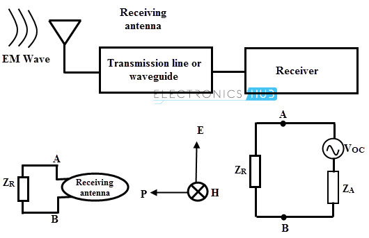
At the receiving end energy and signal from the electromagnetic wave is extracted. An antenna is used to capture the radiated energy is referred as a receiving antenna.
Thus, from the incident electromagnetic wave, a receiving antenna transfers a part of energy in the form of voltage (between antenna terminals) to the load. In complex notation and in the frequency domain, a receiving antenna acts as a voltage generator with internal impedance.
The symbolic representation of receiving antenna can be described the Thevenin’s equivalent as shown in figure. The internal impedance of the transmitting antenna (Thevenin’s generator) is same as the impedance of the antenna when transmitting if there is no emf present at its terminals.
Hence, the properties of a receiving antenna can be assessed by what properties that the same antenna can hold when it is transmitting. Most frequently same antenna can be used for both receiving and transmitting, as an example in case of mobile phones same antenna used for both way communications.
The Thevenin emf across the terminals of a receiving antenna depends on the shape of the antenna and the direction of incident electromagnetic wave exciting it.
The direction and polarization of the incident wave greatly influence the emf induced in the receiving antenna, although the impedance of the receiving antenna depends on antenna characteristics. Thus, receiving antenna also has directional properties which are same as those when it is used for transmission.
Different Type of Antennas
A wide variety of antennas used for different purposes which are rated at different frequencies. Antennas can be classified into several types based factors like frequency band, electromagnetic design, physical structure, etc. and this classification is given below.
Based on Frequency and Size
If an antenna efficiently transmits as well as receives the waves of frequencies in a relatively narrow frequency range, then such antenna is said to be narrow band. Similarly if antennas operate in a broader frequency ranges then such type of antennas are called as broadband antennas. Additionally antennas are given with frequency range in which they are used. These are
- Low frequency antennas: 30 KHz to 300 KHz
- Medium frequency antennas: 300 KHz to 3 MHz
- High frequency antennas: 3 MHz to 30 MHz
- Very high frequency antennas: 30 MHz to 300 MHz and
- Ultra frequency antennas: 300 MHz to 3000MHz
Based on Directivity
These are again classified into three types as
Omnidirectional Antennas
These types of antennas include quarter-wave antenna and half-wave dipole antenna. This kind of antennas radiates the energy equally in the all directions around the antenna in case of transmission and also at receiving end picks up the signals from all directions. The better will be the antenna performance if it is longer omnidirectional antenna.
Sectorial Antennas
These antennas radiate the energy mainly in a specific area. The beam of sectorial antennas can be as narrow as 60 degrees and as wide as 180 degrees. These are used for limited range distances around 5 to 6 km. The best example is the Wi-Fi networks in mobile communications.
Directive Antennas
These are called as directional or beam antennas which radiates the power in one or more directions around the antenna. These allow the increased performance in both receiving and transmitting the signals with reduced interference from unwanted sources.
These antennas are used for long distances due to its highest gain. Some common directive antennas include Yagi-Uda antenna, horn antenna, Bi-quad antenna, patch antenna, helical antenna, parabolic antenna and many others.
According to the Application
Based on application, antennas are mainly categorized into two types; namely base station antennas and point-to-point antennas. Base stations are used for multipoint access and for this purpose it uses either sectorial antenna (which focuses on a limited area) or omni antennas (which radiate equally in all directions).
Point-to-point antennas are used to connect two single locations together and in such cases, directive antennas are used.
Based on Aperture
Aperture antennas receive and transmit energy from its aperture. These types include
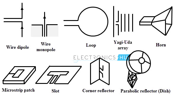
Wire Antenna
It is simply a wire of length l/2 (which is a dipole antenna) and l/4 (which is a monopole antenna), where l is the transmitted signal wave length. These antennas can be loop antennas such as rectangular loop antenna, circular loop antenna, etc. The best example of wire antenna is a whip antenna.
Horn Antenna
These antennas are regarded as opened out or flared out waveguide. Based on flaring, sectorial horn, or pyramidal horn, or conical horn type antennas are formed in the respective waveguides.
Parabolic Reflective Antenna
This antenna consists of a primary antenna such as horn or dipole situated at the focal point of a paraboloid reflector. This arrangement of this antenna implies that reflector can focus parallel rays onto the focal point or in other hand; it can produce a parallel beam from radiations originating from the focal point.
Cassegrain Antenna
In this antenna, Instead of placing the primary feed radiator at focus, it is positioned around the opening near the vertex of the paraboloid. Compared to simple parabolic antenna, these antennas are less prone to back scatter.
Microstrip Patch Antenna
These are specially designed antennas for specific applications such as aircraft or space craft applications in order to meet the specifications like size, performance, weight, installations, etc. But the major disadvantages of these antennas are low efficiency and very narrow bandwidth.
