In the previous tutorial we have seen binary encoders which encode the given data. But a standard digital encoder has one limitation that it would produce an error at its output if more than one input is active at a given time. It generates an undefined combination of outputs, if the two inputs are logic 1 simultaneously.
Consider in case of 8 to 3 line encoder in which, if D2 and D5 are 1 simultaneously, the encoder produces the output as 111 that means all three outputs are equal to logic 1 (as an example in case of a person operating keyboard might press a second key before releasing the first). This value does not correspond to either binary 2 or binary 5.
To overcome this problem, encoder circuit must establish a priority such that only one input is encoded at such cases. This means that whenever two inputs are equal to logic 1 simultaneously, then the encoder must prioritise the level of each input such that it produce output corresponds to highest priority input. Such an encoder is called as priority encoder.
Priority Encoder
As said before , a priority encoder is one of the types of encoders in which an ordering is imposed to the inputs that means compared with the standard encoder, it includes the priority function.
However, this priority is based on the relative magnitudes of the inputs. Hence, the input with larger magnitude is the one that is encoded first.
Priority encoders can select the inputs with highest priority in many practical applications. This process of selection is called arbitration.
One of the most common examples of arbitration is that , there are numerous input devices in computer system and several of which devices attempt to supply the data to the computer simultaneously. In those cases, a priority encoder enables the input device having the highest priority among those devices trying to access the computer at the same time.
Let us see the design of 4 input , 8 input priority encoders.
Simple 4-Input Priority Encoder
This Priority encoder consists of 4 inputs and three outputs. Although an encoder has 2n inputs and n outputs, it has a third output ‘V’ which is a valid bit indicator and is set to one when one or more inputs are active or equal to 1.
This valid bit is zero when all the inputs are zero which indicates that there is no valid input. On this condition, other outputs are considered as don’t care conditions and are not inspected when V is zero.
The highest will be the priority of the input with a higher subscript number according to the truth table that is most significant bit will have highest priority while the least significant bit will have low priority .
In the truth table, D3 has the highest priority and D0 has lowest priority. When D3 is active or 1, then regardless of other inputs, the output is 11. The next higher priority is D2 after D3.
The next higher priority is D2 after that D1. Thus, when D3 is 0 and D2 is 1 then regardless of other two inputs (which has lower priority), the output is 10. When higher priority inputs are zero then the output for D1 is generated and so on down the priority levels.
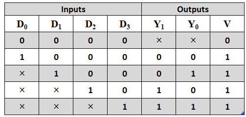
From the above truth table we can write the Boolean expression for the two outputs as
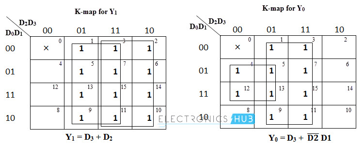
K-map Simplification
The above expressions for the intputs and valid output can be obtained by using the K-map simplification. Although the truth table of this encoder is shown with five rows, we can obtain 16 input combinations when each × in each row is replaced first with zero and then by one. The min terms of the two outputs can be derived as
Y1 = ∑ m (1, 2, 3, 5, 6, 7, 9, 10, 11, 13, 14, 15)
Y0 = ∑ m (1, 3, 4, 5, 7, 9, 11, 12, 13, 15)
Then from the below K-maps we obtain the outputs as
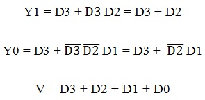
Y1 = D3 + D2
Y0 = D3 + (D2) ̅ D1
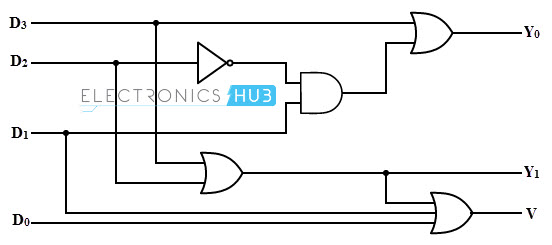
The logic diagram of 4-input priority encoder is implemented by corresponding output expressions obtained from K-map simplification. A circuit diagram of this encoder is shown below.
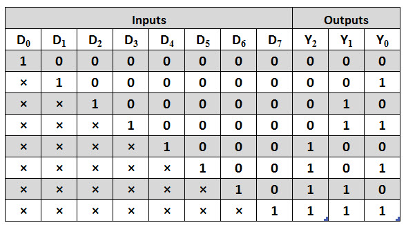
8 – to – 3 Priority Encoder or Octal – to – Binary Priority Encoder
The truth table of an octal – to – binary priority encoder is shown below. This type of encoder has 8 inputs and three outputs that generate corresponding binary code. A priority is assigned to each input so that when two or more inputs are 1 at a time, the input with highest priority is represented in the output.
Suppose if the input lines D2, D4 and D7 are logic 1 simultaneously irrespective of the other inputs, only D7 will be encoded and the output will be 111. Similarly, if D3 = 1, the state of D2, D1 and D0 is irrelevant or don’t care and the output is equal to 011.
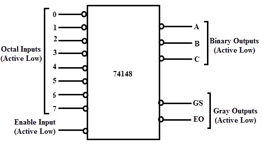
An IC 74148 is the most popularly used MSI encoder circuits for the 8 to 3 line priority encoder. The main characteristics of this encoder include cascading for priority encoding of n bits, code conversion, priority encoding of highest priority input line, decimal to BCD conversion, output enable-active low when all the inputs are high, etc.
The inputs of digital circuits often use octal code so there will be a need of entering such long binary words manually. Thus, the encoder IC is designed to achieve such operation.
The below figure shows its pin diagram and it has active low inputs and active low outputs. To handle more inputs, these ICs are cascaded by enabling input and gray outputs which are also active low lines.
Decimal- to- BCD Priority Encoder
This type of encoder performs the same operation as that of a normal decimal to BCD encoder as encoding the decimal digits into 4-bit BCD outputs. However, it consists of an additional functionality of providing priority. That means the BCD output is produced corresponding to the highest priority of a decimal digit appearing on the inputs irrespective of all other inputs.
The figure below shows the truth table of a decimal – to –BCD encoder. This encoder has nine active low inputs representing the decimal digits from 1 to 9. According to the highest order activated input, it produces the inverted BCD code.
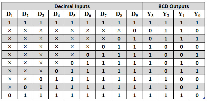
When all the inputs from D1 to D9 are logic 1, all the outputs are set to 1111 which is the inverse of 0000, i.e., BCD code for 0. When D9 is 1, the output is 0110, which is the inverse of 1001, i.e., BCD code for 9. This procedure is same for all the decimal numbers.
The outputs are normally high when none of the input is activated and this case corresponds to the decimal 0 inputs. Thus, when all the inputs are high, the encoder assumes the decimal 0 state as there is no D0 input.
Also, if the two inputs are activated at the same time, suppose D3 and D5 then the highest priority of these inputs, i.e., D5 is encoded as 1010 which is the inverse of 0101, that’s how this encoder is called as priority encoder.
16 to 4 Priority Encoder
Similarly, a 16 to 4 encoder can be constructed by using six 4 to 2 encoders. Four 4 to 2 encoders are connected to the 16 inputs and the 8 outputs are again connected to the two 4 to 2 encoders , which produces 4 outputs.
Priority Encoder applications
As compared with the standard digital encoder, a priority encoder is most commonly used in several applications. A larger priority encoder is designed by cascading the several priority encoders. Therefore, this type of encoders is used to reduce the number of connections required in a particular application in which there are multiple inputs are present.
Keyboard Encoders
Assume that a QWERTY keypad is interfaced with microcomputer and hence computer has to read the 104 keys of the keyboard such that at any time it would read only one key pressing as either High or LOW.
It is not possible to connect all these 104 connections directly to the computer (if it is of less configured), however it is a more effective way to connect them by the use of priority encoder. By using this encoder, each character or key is encoded into a standard ASCII code of 7 bits (0-127 decimal) from
all these 104 keys or individual buttons. Then it inputs 7-bit BCD code to the computer. One of such type of keyboard encoder is 20 key, 74C923. And also these encoders provide the facility of priority such that when two keys are pressed at the same time, it gives the highest priority inputs.
Positional Encoders
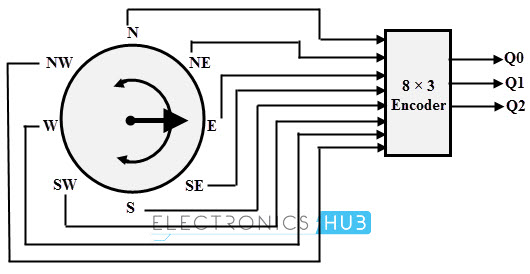
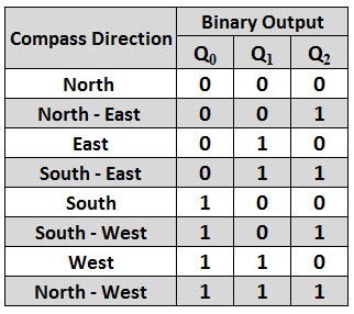
A magnetic positional control is another common application of priority encoders. Such control is used in robotic arm positioning and ship navigations. In such cases, encoder converts the rotary or angular position of a compass to a digital code. Then this code is input to the computer so that the navigational data is provided.
Below figure shows the simple compass encoder that converts the 8 positions to 3 bit output. For this type of input –output configuration, a 74LS148 IC is used which is an 8-to-3 line priority encoder. For indicating the compasses angular position, generally reed switches and magnets are used.

One Response
i want truth table and circuit design for 2×4 MSB priority encoder.