Power factor is a significant parameter in a power system network as well as in all electrical equipments, which decides the efficiency of the power transmission or utilisation.
A poor or low power factor increases the current, resulting in additional losses on the power system components right from generating stations to end consumer installations. It must be maintained close to unity for the economical and efficient distribution of electrical energy.
What is Power Factor?
Power factor is defined as the cosine angle between voltage and current in an alternating current (AC) circuit. Unlike in DC circuits, a phase angle difference, ϕ exists between voltage and currents in an AC circuit. The cosine of ϕ (or Cos ϕ) is termed as the power factor.
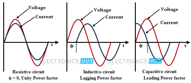
If the circuit consists of inductive elements or it behaves like an inductive circuit (where current lag behind the voltage), then the power factor in that circuit is referred as a lagging power factor.
On the other hand, if the circuit is capacitive in nature where current leads the voltage, then the power factor is referred as the leading power factor. If there is no phase angle difference between the voltage and current then it is unity power factor.
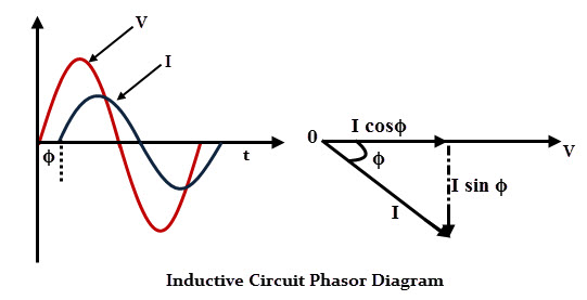
Consider above waveforms and phasor diagram of an inductive circuit where current lags the voltage by an angle ϕ. Here, the total current is resolved into two components.
The I cos ϕ component is called wattful or active component and it is in phase with the source voltage. The I sin ϕ component is called wattless or reactive component and it is 900 out of phase with the source voltage.
From the figure we can say that the angle from these two components decides the power factor, and it implies that if the reactive component is small, the phase angle ϕ is small resulting high power factor (In every electric circuit, power factor should be maintained high for a better utilization of power). Thus, a small reactive current in the circuit results a high power factor and vice-versa.
It is to be noted that the power factor can never be more than unity. The most efficient loading of the supply results a power factor of 1. Suppose, if the power factor of the load is 0.8 means there are much higher losses in the supply system.
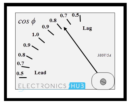
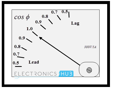
Generally power factor is indicated with words lagging and leading, in addition to the value. This is to represent whether current leads or lags by the voltage. For example, 0.8 lagging implies that the circuit has a power factor of 0.8 where current lags the voltage. Sometimes, it is also indicated as a percentage such as 80% lagging.
Power factor can also be expressed in terms of power consumed by electrical equipment or a complete electrical installation. In such case power factor is defined as the ratio between the true power (KW) to the total apparent power (KVA).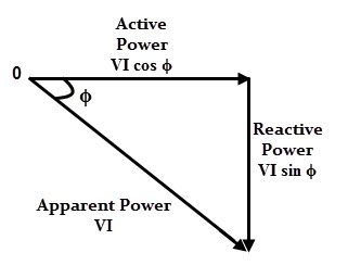
Consider the above power triangle which gives the relation between various powers. The VI cos ϕ, component is called true or active power which is measured in watts (W) or Kilowatts (KW). It causes useful work in the circuit.
he VI sin ϕ, component is called wattles or reactive power and it is measured in volt-amperes-reactive (VAr) or kilo-volt-amperes-reactive (kVAr). It is caused by inductance or capacitance in the circuit and it does two main functions; to provide magnetic field and to charge capacitors.
The resultant component of true and reactive or simply a VI component is called apparent power and it is measured in volt-amperes (VA) or kilo-volt-amperes (kVA).
From the figure, power factor, cos ϕ = active power/ apparent power = VI cos ϕ/ VI
cos ϕ = KW/KVA
The above expression of power factor measures how efficiently electric power is converted into useful work output. And also, from the power triangle, reactive power component measures the power factor. If the reactive power component is small, the power factor will be high and vice-versa.
From the above discussion, the power factor can be expressed in following ways
- Power factor = cos ϕ = cosine angle between voltage and current
- Power factor = VI cos ϕ/ VI = KW/KVA
- Also, Power factor = Resistance/ Impedance = R/Z
Effects or Disadvantages of Low Power Factor
Before going to know the disadvantages, let us consider following calculations.
Suppose, a motor is rated at 200 V and 1KW and it is operating at two different power factors, i.e., 0.5 and unity. The current to the motor in each power factor operation is given as
At unity power factor, I = (1000/ 200 × 1) since P = VI cos ϕ
So the current flowing through the motor at unity power factor, I = 5 A
Also, apparent power = VI = 200 × 5 = 1KVA
At 0.5 power factor, I = (1000/ 200 × 0.5)
So the current flowing through the motor at 0.5 power factor, I = 10 A
Also, apparent power = VI = 200 × 10 = 2 KVA
The causes of low power factor include various inductive loads such as induction motors, power transformers, induction furnaces, welding transformers, ballast of illumination equipment, etc.
Due to high harmonic content or distorted current waveforms obtained by various electronics loads also cause the low power factor. Some of these loads include inverters, rectifiers, variable speed drives, SMPS, etc.
The disadvantages of low power factor are given below.
Greater cable size
The current flowing through conductors or cables during low power factor is higher than the current at a high power factor.
In the above example, the conductors have to carry twice the current of the motor at a low power factor when compared with unity power factor. Larger cables are required to carry a larger current during low power factor condition of the load.
Larger KVA rating
KVA rating of the equipment increases with decreasing of power factor. From the above calculations the KVA rating is 1at unity power factor and 2 at 0.5 power factor.
Alternatively cos ϕ = KW/KVA where KVA rating is inversely proportional to the power factor. Hence the KVA rating of the equipment has to be made more at a low power factor. This results the equipment larger and more expensive.
More copper losses
As the larger currents flow through the equipment or installed power system network at low power factor, more will be copper losses (I2R) in the system and hence it leads to poor efficiency.
More electricity tariffs: Low power factor increases electricity bills due to higher consumption of current. Sometimes the electricity company penalizes for low power factor, because the company must install transformers, cables and other equipment to supply the apparent power (KVA) but not the true power (KW).
Poor voltage regulation: Low power factor causes larger voltage drops in transmission and distribution lines, transformers, alternators, etc. This results in decreased voltages in the supply end.
Power Factor Correction Methods
The advantages of power factor improvement include reduction of power consumption, improved energy efficiency, reduction of electricity bills, extra KVA availability from the existing supply, reduction of voltage drop in the lines, extended equipment life and reduced power losses.
Power factor is improved by connecting some devices (such as capacitors) that take leading currents, in parallel to the load operating with poor power factor. There are different methods available for improving the power factor. Some of these methods are discussed below.
Power Factor Correction by Static Capacitors
Capacitors oppose the inductive effect of the loads or motors by drawing leading currents. These are connected in parallel with the load to be corrected so that lagging reactive power component of the load current is completely or partially neutralised.
In this method, static capacitors may be connected across individual motor loads, or in a bank at transmission or distribution substations.

The individual system of capacitors gives a more accurate correction of power factor as the capacitor operates when the motor is in use.
In case of a capacitor bank system, various capacitors are automatically controlled depending on the correction required. In case of three phase loads, capacitor banks are connected in star or delta modes as shown in figure.
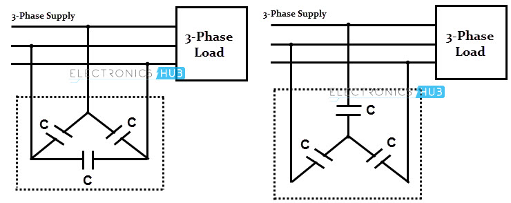
This method is widely used in industries and substations. As there are no moving parts in this, it requires less maintenance. However, repair of capacitors is not economical, once they are damaged.
Power Factor Correction by Synchronous Condenser
Synchronous condenser is a rotating machine which is similar to the synchronous motor, but the shaft of the motor is not brought out of the case. Due to very little shaft load, the machine demands very little active power.
The field excitation of this motor is varied to produce different power factors. When the synchronous motor is over-excited, it behaves like a capacitor (property of taking of leading current).

An over-excited synchronous motor operating at no load is termed as synchronous condenser. When it is connected in parallel with the load that operating at low power factor, it takes the leading current, thereby it neutralizes the lagging reactive component of the current similar to a capacitor.
Synchronous condenser has a stationary three-phase armature winding which is connected to the load terminals where the power factor has to be improved.
And its rotating field is excited from a DC supply (which is drawn from three phase supply and then by rectification), sometimes it is provided by a small DC generator which is mounted on the shaft of synchronous condenser.
So the amount of rotor field current of synchronous condenser is controlled by the amount of DC excitation provided by the DC generator, in other words the amount of power factor correction is controlled by the amount of DC excitation.
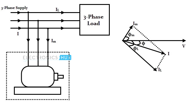
In the above phasor, the load current IL lags the voltage by an angle ϕL and the current through synchronous condenser leads the voltage by an angle ϕM.
So the sum of IL and Im gives the resultant of current I that lags the voltage by angle ϕ. From the figure it is clear that the angle ϕ is less than ϕL and hence cos ϕ is greater than the cos ϕL. So the power factor is improved by this method.
This method achieves the step control of power factor by varying the field current of the synchronous condenser.
However, this method struggles with some disadvantages such as high maintenance cost, considerable losses in the motor and need of auxiliary equipment to start the motor (as the synchronous motor is not self starting).
Power Factor Correction by Phase Advancers
The method correcting the power factor by Phase advancers is mainly used for of induction motors. This is because the power factor of an induction motor is very low due to high lagging nature of windings where field current lags the voltage somewhat closer to 900.
If this filed current is supplied from some other AC source, the motor won’t take field current from the mains and hence the power factor is improved.
This job is performed a phase advancer which is a small commutator machine mounted on the shaft of the induction motor and it is connected to the rotor to supply the field current at slip frequency.
When the phase advancing machine provides more current or ampere turns than required, the induction motor takes the leading currents (since it acts as an over-excited synchronous motor) and hence the power factor is improved. This method is not economical for motors that are rated below 200 H.P.
