We know that small signal diodes are used in several applications like current steering, over voltage protection, switching circuits, clipping circuits, clamping circuits, snubbing the small duration waveforms and the most important of all: power conversions (from AC to DC). Small signal diodes conduct current solely in one direction: from anode to cathode and this is the most important property used in converting alternating current to direct current. This process of current conversion is called as Rectification and the circuits used are called Rectifiers.
But due to the large amounts of forward current and revere bias voltage, small signal diodes may be overheated and get damaged in the process of rectification. In such cases, Power Semiconductor Diodes are used to overcome the excess currents and voltages.
A Power Semiconductor Diode is a crystalline semiconductor device, also known as Power Diode, used mainly for the purpose of rectification. This type of rectification process is mostly seen in all power supplies of modern-day electronic and electrical apparatus. Similar to small signal diodes, a power diode also conducts current only in one direction which is regarded as its forward direction, but doesn’t conduct current in the reverse direction. Power diode’s function seems to be analogous to a mechanical/electrical one-way valve.
Power diodes have very much larger P-N junction area, as a result, they have higher forward bias current carrying capacity than the smaller semiconductor signal. Power diodes are typically capable of passing several kilo amps (KA) of forward current and several kilo volts (KV) of reverse voltage. This makes power diodes better suited for applications where large amounts of currents and voltages are of concern than their small signal or low power counterparts.
Power diodes can be rated based on their two important characteristics: the maximum current that they can be able to carry in the forward direction and the greatest amount of reverse bias voltage they can withstand. Due to the ON resistance of the power diode, a small voltage drop occurs during the conduction of current. On the other hand, a power diode can withstand a definite amount of reverse bias voltage before the breakdown condition where it ceases to function.
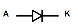
Power diode symbol
The symbol of power diode is shown below. The symbol is similar to a normal diode but the anode and cathode are mentioned as A and K respectively.
The structure of Power Diodes is slightly different from small signal or low power diodes. The structure of a typical diode is shown below.
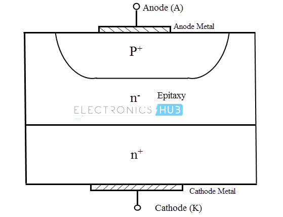
There is a heavily doped n+ region that forms the cathode of the diode. On this, there is a lightly doped n- epitaxy. In this epitaxy, a heavily doped p+ region is diffused in order to form the P-N junction. This p+ region forms the anode of the diode. The epitaxy, also known as Drift layer, will decide the junction area. When forward biased, the drift layer adds a remarkable amount of Ohmic resistance to the diode as it is lightly doped. Its width determines the reverse breakdown voltage.
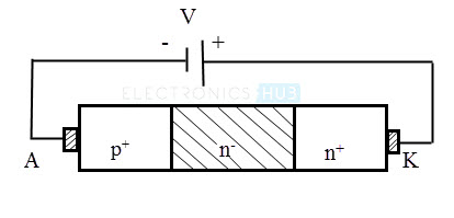
Power diode in forward bias
When the power diode is forward biased, the excess P type carriers from anode are injected into the n- epitaxy layer. At high level of injection, these excess P type carriers will reach the n- n+ junction and attracts the electrons from the cathode i.e. n+ region. Now the electrons are injected into the n- region (drift region). This phenomenon is called Double Injection. Excess P type carriers from anode and excess n type carriers from cathode defuse and recombine in the n- epitaxy region (drift region). The consequence of this is Conductivity Modulation where the conductivity of the drift region is considerably increased. This makes the I V characteristics of the forward biased power diode more linear.

Power diode in reverse bias
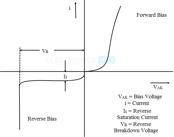
Like a normal diode, a power diode also doesn’t conduct when reverse biased. Only a small amount of reverse leakage current flows in the reverse direction. For a power diode that is rated with 1000 A of forward current, only 100 m A of reverse current flows. At breakdown voltage, the reverse current increases rapidly due to impact ionization and avalanche multiplication.
The i v characteristics of power diode are shown in the following graph.
Power diodes are primarily manufactured with Silicon but Gallium arsenide is also used sometimes. Materials such as Phosphorus, Arsenic and Germanium are used as dopants to form the anode (n+) while Boron, Aluminium and Gallium are used as dopants to form the cathode (p+).
Power diodes are designed to offer uncontrolled power rectification and can be used in the applications like charging of the battery, DC power supply and high voltage direct current power transmission systems as well as in rectifiers of AC circuits and in inverters. Because of their high current and high voltage characteristics they are also used as fly wheeling diodes and in waveform snubbing networks. As the power diode has a very large P-N junction area, it may not be suitable for high frequency applications i.e. for frequencies greater than 1 Mega Hertz; however design of high frequency and large current diodes is desired. Schottky Diodes are typically used for the application like high frequency rectification. The reason being their low reverse recovery time and voltage drop when forward biased.
If a single power diode is used in converting AC to DC, then it produces a half-wave varying DC. If more than one diode is used in a circuit, it produces a full-wave varying DC as it converts both positive and negative halfs of a varying AC wave into varying DC, therefore producing full-wave rectification of current. A Bridge rectifier is a type of full-wave varying DC circuit, where four diodes are connected. It provides a similar polarity output for either of the input polarities. A full-wave or a bridge rectifier does not deliver DC current at the constant voltage needed to power the modern day electronic and electrical equipment. As a result, a smoothing capacitor is usually connected at the output of the rectifier in order to smooth out the rippled voltage produced.
Power diodes use different types of IC packages. Typical examples may include the following
- DO – Diode outline
- SOD – Small outline diode
- TO – Transistor outline
- SOT – Small outline transistor
- Metal electrode leadless face.
D2PAK – Discrete package is a huge surface mounted package which also includes a heat sink in it.
The data sheet of a power diode includes the following.
1. Forward Average current
2. Forward RMS current
3. Average Forward Power loss
While designing rectifiers using power diodes, we should never exceed these parameters.
Power Diode Rectifier
Structurally, rectifiers can take a multiple forms, which include olden day’s vacuum tube diodes, copper and other metal oxide rectifiers and mercury arc valves. With the introduction of semiconductor electronics in recent days, rectifiers are mostly constructed from semiconductor diodes, thyristors or silicon controlled rectifiers (SCRs) (a type of thyrister) and other silicon based semiconductor switches. The process of Rectification may also serve as a source of power besides generating the direct current. As a point of note, the detectors of radio signals also serve as rectifiers. Because of the flashing and varying nature of the AC sine wave, the rectification process alone itself produces a DC current which is unidirectional also consists of pulses of current. Many applications of rectifiers include power supplies for radio, television, computer and other electronic communication equipment which require a stable and constant DC current. In these electronic applications, the output of the rectifier is smoothed by an electronic smoothing filter or a capacitor to produce a constant form of current.
In the rectification from very low to high currents, various kinds of semiconductor diodes such as junction diodes and Schottky diodes, etc., are broadly used. Various types of silicon based semiconductor devices are used in high power rectifiers, such as those used in higher voltage direct current power transmission systems. The silicon based semiconductor devices include thyristors and many other controlled solid state switches effectively function as diodes to pass direct current solely in one direction.
Rectifier circuits can be classified as either single phase or multi phase based on the type of the alternating current. Most of the low to medium power rectifiers for household equipment are single phase whereas three phase rectifiers are very crucial for industrial applications and also in the process of transmission of energy as DC.
A variety of rectifier circuits are available today. They may be Half Wave, Full Wave and/or Bridge Rectifiers. Each type of these rectifier circuits can be categorized as either uncontrolled, a half-controlled or a fully controlled device.
Features of Power Rectifiers
- Simplified mechanical designs and fast assembly
- High surging capability
- Large creepage distances
- Designed and trained for industrial applications
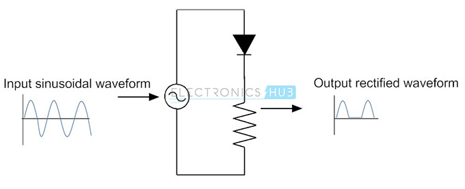
Half Wave Rectification
Rectification may be defined as the process of converting the alternating of current into direct current. The power supply to the rectifiers may be either single phased or multi phased alternating current. Consider the simple case of Half Wave Rectifier of a single phase supply. If the AC sine wave is applied to it as input, then either the positive or negative half of the AC sine wave is passed (depending on the forward bias condition of the diode) by blocking the other half of the sine wave. As only one half of the input waveform reaches the output during the forward bias, the mean voltage across the resistor is lower than the usual.
Half wave rectification with a single phase supply or a multi phase supply requires only a single diode. Rectifiers will result in a unidirectional and pulsating direct current. Half wave rectifiers produce more amounts of ripples than the full wave rectifiers, and a smoothing capacitor is required to eliminate the AC harmonic frequency from the DC output. The diode used in half wave rectification might be any of the 1N400X series of rectifying diodes.
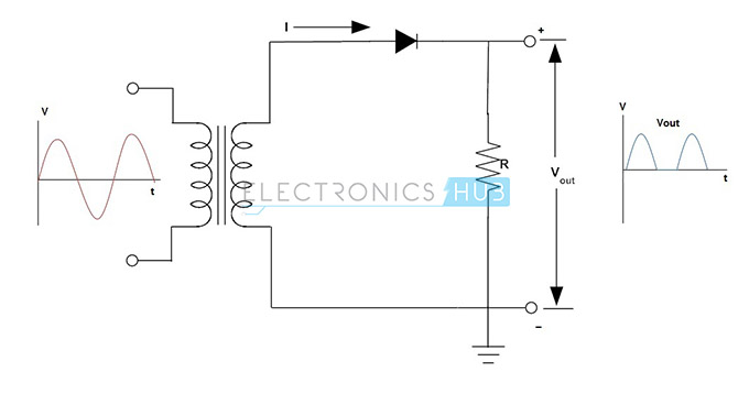
The DC load present at the end of the circuit is a resistor, therefore the current flowing through the load resistor is proportional to the voltage across the resistive load and this would be the same as the supply voltage. The DC voltage resulting across the load is sinusoidal for the first half cycle i.e.,VR= Vs.
During the negative half cycle of the input AC sinusoidal waveform, the diode will be reverse biased. Therefore, no passing of current takes place through the diode or in the circuit. As a result of it, for the negative half cycle input, no current flows through the resistive load as there will be no voltage appears across it.
Vout = 0
When the load resistor receives an alternative positive half of the waveform and alternative zero volts, then the value of this alternative irregular voltage can be viewed as an equivalent DC voltage of 0.318 * VPEAK of the input sine waveform or it can be 0.45 x Vrms of the input sine waveform, where
Vrms = VPEAK/√2
Half wave rectification is not of much use as the output signal will be available in bursts and is discontinuous. The best application of half wave rectifier for house hold purposes is a two level lamp dimmer. Half wave rectification is not much effective in producing DC output from a 50Hz or 60Hz AC input. In addition the gap between the output pulses of diode current makes it more difficult to eliminate the AC ripple that remains after the rectification process.
Half-wave Rectifier with Smoothing Capacitor
In the process of rectification from an AC current to DC current, the amount of ripples present in the DC output will be greatly reduced by placing a capacitor in parallel with the resistive load. The capacitance of the capacitor should be very high in order to eliminate great amounts of AC harmonic frequencies in DC output, but the cost and size of the capacitor should be less.
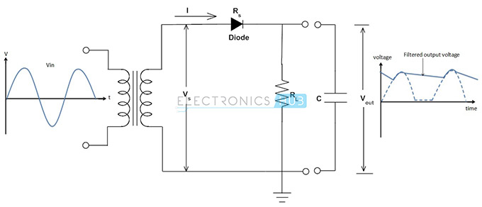
For a given capacitance value, if the load current through the resistive load is very high, the capacitor discharging will be greater and ripples in the DC output also increases. As a result, half-wave rectifier circuit using a single phase is not very practical to reduce the ripple voltage in the DC output by using a single smoothing capacitor alone. At this moment it would be more usual to use full wave rectification instead of half wave rectification.
In half-wave rectifiers, the output amplitude will be less than the input amplitude and there will be no output during the negative half cycle so half the power is wasted and the output is pulsed DC, resulting in excessive ripples. In practice, the half-wave rectifiers are used most often in low-power applications because of their major disadvantage of power wastage. To overcome this, a number of power diodes are connected together to produce a Full Wave Rectifier.
Full Wave Rectification
A full wave rectifier circuit converts the whole of the input sinusoidal waveform to one of the polarity either positive or negative as its output. Full wave rectification converts both polarities of the input sine waveform to a pulsative direct current. The average output voltage at the resistive load is very high. Two power diodes with a centre tapped transformer or four power diodes in bridge type configuration without any centre tapped transformer are needed for full wave rectification. If the transformer that has a secondary winding with a centre tap is used, then the greater efficiency in full wave rectification can be achieved
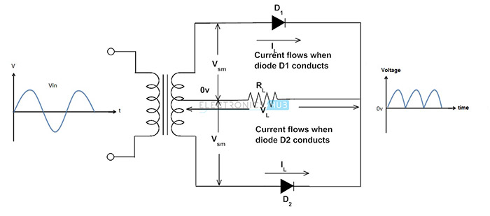
If each of the anti – phase outputs is half wave rectified by one of the two diodes, with each diode letting them to conduct on alternate half cycles, there occur two pulses of current for every cycle, in contrast to one pulse per cycle in half wave rectifier. The frequency at the output of full wave rectifier is consequently, twice that of the input frequency and also the output voltage of full wave rectifier is twice that of the output voltage of half wave rectifier i.e. the output DC is equivalent to VPEAK x 0.637 instead of VPEAK x 0.318, because the missed half wave cycle is rectified now, reducing the amount of power shattered when compared tothe half wave rectifier circuit. The higher output frequency of full wave rectifier circuit also makes the smoothing of any remaining AC ripples easier in the output waveform. Since the output is not the required pure DC output, the quality of the output can be measured by a quantity known as the Ripple Factor. It can be defined as the ratio of the difference in maximum to minimum voltages to the average voltage of the DC output waveform.
Ripple Factor = (Max-Min)/Average

Bridge Rectifier
Another type of rectifier circuit that produces the similar DC output waveform as a full wave rectifier circuit is a full wave bridge rectifier circuit. As the name indicates, the full wave bridge rectifier requires four power diodes arranged as a bridge circuit as shown in figure to give full wave rectification without any need of a centre tapped transformer. It has to be observed for each and every half cycle, the diodes in opposite pairs will conduct, while the amount of current flowing across the load remains in the same polarity for both the positive and negative half cycles. Diodes D1 and D2 conduct for the positive half cycle of the input (AC supply) while D3 and D4 conduct for the negative half cycle.
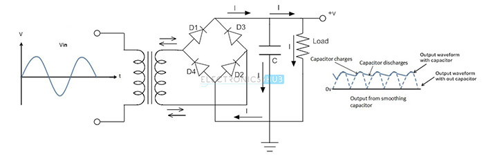
To eliminate the ripples present in the DC output waveform, the smoothing capacitor having a typical value of 100 micro Farads or more should be used. In choosing the smoothing capacitor, the parameters that should be kept in mind are the working voltage and capacitance value. The value of working voltage should be greater than the output value of rectifier when no load is connected.
