Consider a task of moving a charge from A to B in a uniform electric field. Let this movement be against to the electric field. Some work will be done by an external force on this charge and this work will change the potential energy to a higher value. The amount of work done is equal to the change in potential energy. This change in potential energy will result in a difference in potential between the two points A and B. This difference in potential is called Potential Difference and it is measured in Volts (V).
Potential Difference Definition
Potential Difference is denoted by ∆V and is defined as the difference in potential or voltage between two points.
If VA is the potential at A and VB is the potential at B, then from the definition of potential difference,
∆VBA = VB – VA
For example, consider the following resistor R1.
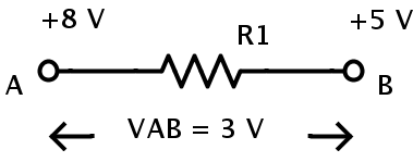
The potential applied at one end of the resistor (Point A) is 8 V and the potential at other end of the resistor (Point B) is 5 V.
The potential difference between the two points A and B is
VAB = 8 – 5 = 3 V.
This is also called as the Potential across the resistor.
Current flows in an electrical circuit in the form of charge whereas potential doesn’t flow or move. Potential difference is applied between two points.
The unit of potential difference between two points is Volt. Volt is defined as the potential drop across a 1 Ohm (Ω) resistor with 1 Ampere of current flowing through it.
Hence
1 Volt = 1 Ampere×1 Ohm
V = I × R
According to Ohm’s law, the current flowing in a linear circuit is directly proportional to the potential difference across the circuit. Hence if the potential difference applied across the circuit is greater, then the current flowing in the circuit is larger.
For example if one side of a 1 Ω resistor is at a potential of 8 V and the other side is at 2 V, then the potential difference across the resistor is 5 V. The current flowing in the resistor is
I = V/R= 5V/1 Ω = 5 Amps.
Now for the same 1 Ω resistor, if the potential applied at one end is raised from 8 V to 12 V and at the other end it is raised from 2 V to 4 V. Then the potential difference across the resistor is now at 8 V. The current flowing in the resistor in this situation is 8 Amps.
I = V/R= 8V/1 Ω = 8 Amps.
Generally in electrical circuits the lower potential is earth or ground. This value is usually considered 0 V. Hence the potential difference is equal to the applied voltage. Earth is considered as the common point in a circuit. This reference of earth or ground as common point in electrical circuits is useful in easy understanding of the circuit. Potential difference is also called voltage.
Voltages connected in series are added to give total voltage in a circuit. This can be observed in resistors in series connection. If V1, V2 and V3 are connected in series then total voltage VT is given by
VT = V1 + V2 +V3.
In case of elements connected in parallel, the voltage across them is equal. This can be observed in resistors in parallel tutorial.
VT = V1 = V2 = V3.
Potential Difference Examples
- If 1500 Joules of potential energy is transferred to move a charge of 125 Coulombs between the terminals of a battery, then the potential difference is
∆E = 1500 J
Q = 125 C
Potential difference V = ∆E / C
V = 1500 / 125 = 12 Joules / Coulomb = 12 V
2. Consider a resistor of resistance 10 Ω. Let one end of the resistor be connected to a potential of 15 V. Let the other end of the resistor be connected to a potential of 5 V. The current flowing through the resistor can be calculated as follows.
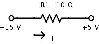
The two terminals of the resistor are at two different potentials i.e. 15 V and 5 V respectively. Let the two terminals be A and B. Therefore the voltage at A is VA = 15 V and the voltage at B is VB = 5 V. Then the potential difference between A and B is the voltage across the resistor.
VAB = VA – VB = 15 – 5 = 10 V.
Then the current flowing across the resistor can be calculated using Ohm’s law as
I = VAB / R = 10 / 10 = 1 Amps.
Voltage Divider Circuit
Resistors in series connection are used to produce a voltage divider circuit. Voltage divider is a linear circuit whose output voltage is a fraction of input voltage.
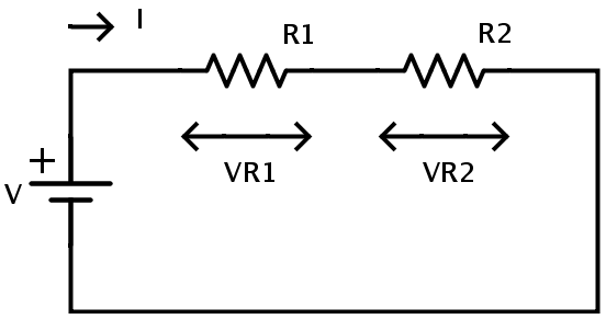
A simple voltage divider circuit with 2 resistors is shown below.
The potential across each resistor in series connection is dependent on the value of resistance.The principle of voltage divider is to produce a voltage that is a fraction of input voltage.
The following circuit is used to show the voltage divider principle for multiple output voltages.
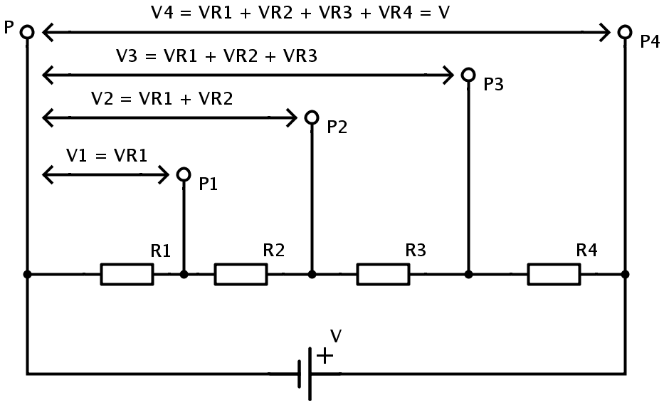
Here the resistors R1, R2, R3 and R4 are in series connection. The output voltage across each resistor is referenced to a common point P. Let the equivalent resistance of the resistors in series is RT. Then RT = R1 + R2 + R3 + R4.
Let the potential difference across each resistor be VR1 , VR2 , VR3 and VR4 respectively for R1, R2, R3 and R4. Then the above circuit can produce 4 different voltages that are fractions of the supply voltage V.
Voltage Divider Formula
The value of the output voltage in a typical voltage divider circuit is calculated as follows.
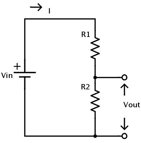
Here Vin is the supply voltage. I is the current in the circuit which flows through both the resistors.
Let VR1 be the voltage drop across the resistor R1 and VR2 be the voltage drop across the resistor R2. Then the sum of these individual voltage drops is equal to the total voltage across the circuit which is the supply voltage Vin.
Vin = VR1 + VR2 – – – 1
The equations for individual voltage drops across each resistor can be calculated from Ohm’s law.
VR1 = I × R1 – – – 2
And VR2 = I × R2 – – – 3
But the voltage across the resistor R2 is VOUT.
Therefore VOUT = I × R2 – – – 4
Therefore from equations 1, 2 and 3
Vin = I × R1 + I × R2 = I × (R1 + R2) – – – 5
But the value of current I in terms of output voltage can be written as follows using the equation 4.
I = VOUT / R2 – – – 6
Using the equations 5 and 6
VOUT = Vin × (R¬2 / R1 + R2)
Therefore VOUT = VIN × R2/(R1+R2)
In case of voltage divider circuit which has multiple outputs,the output voltages can be calculated using the below formula.
VX = V × (RX / REQ)
Where VX is the voltage to be found.
RX is the total resistance across the output voltage.
The possible values of RX are
R1 between P and P1
R1 + R2 between P and P2
R1 + R2 + R3 between P and P3
R1 + R2 + R3 + R4 between P and P4.
REQ is the equivalent resistance of the resistor in series connection.
REQ = R1 + R2 + R3 + R4
V is the supply voltage.
Therefore the possible output voltages are
V1 = V × R1 / REQ
V2 = V ×(R1 + R2) / REQ
V3 = V × (R1 + R2 + R3) / REQ
V4 = V × (R1 + R2 + R3 + R4) / REQ = V
Voltage divider Example
Consider the following Voltage divider circuit.
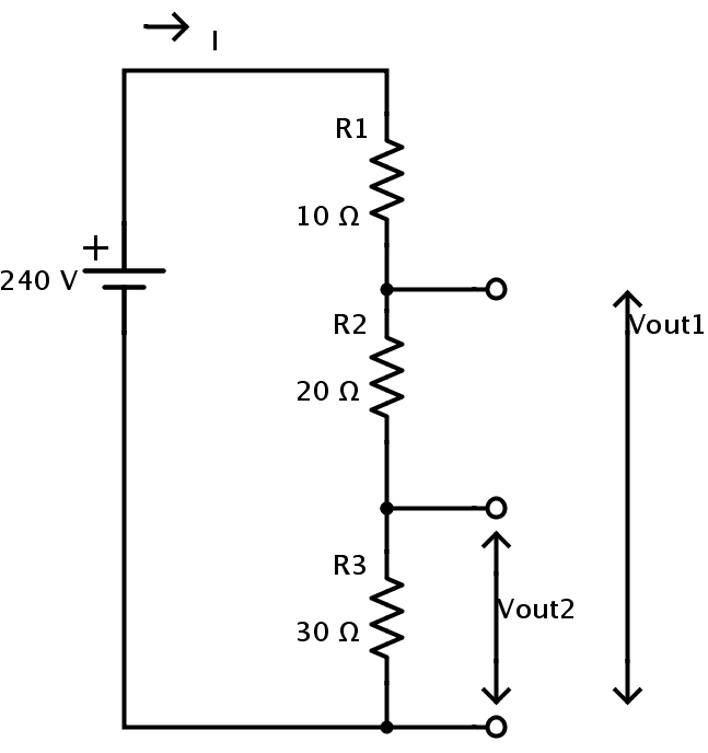
It consists of three resistors connected in series to produce two output voltages. The supply voltage is 240 V.
The values of the resistance are R1 = 10 Ω, R2 = 20 Ω and R3 = 30 Ω.
Therefore the equivalent resistance of the circuit is
REQ = R1 + R2 + R3 = 10 + 20 + 30 = 60 Ω.
Now the two possible output voltages can be calculated as follows
Vout1 = V × (R2 + R3) / REQ
Vout1 = 240 × (20 + 30) / 60
Vout1= 200 V.
Vout2 = V× R3 / REQ
Vout2= 240 × 30 / 60
Vout2 = 120 V.
The current in the circuit is
I = V / REQ = 240 / 60 = 4 Amps.
Therefore the individual voltage drops across each resistor can be calculated as follows
VR1 = I × R1 = 4 × 10 = 40 V.
VR2 = I × R2 = 4 × 20 = 80 V.
VR3 = I × R3 = 4 ×30 = 120 V.
Applications of Voltage Divider Circuits
Resistors in series will form Voltage Divider Circuits. Voltage Divider principle is the basis in the construction of Potentiometer which acts as a simple voltage regulator.
Voltage Divider Circuits are used in Sensing circuits. The most frequently used sensors in the form of Voltage Divider circuits are thermistors and Light Dependent Resistors.

One Response
thanks for that .. great job