The ‘Phasor’ is defined as “The complex number in the polar form with which we can analyze the circuit”. It is a vector quantity. In this vector representation we use Cartesian plane.
The Y axis represents the magnitude and phase angle of the waveform in the form of imaginary quantities and X axis represents real quantities like time period of the wave form. The magnitude of the waveform is generally measured as RMS voltage. So, with phasors, we represent the RMS voltage.
Always the phasors rotates counter clock- wise direction along with the phase of the waveform. In phasor complex number representation includes the magnitude and phase angle of any waveform.
The complex number consists of a real number and an imaginary number. Let’s see about this clearly.
- Real number: The real number in phasor complex number represents the magnitude or amplitude of the signal. It can be also said as the length of the vector.
- Imaginary number: The imaginary number represents the phase angle of the waveform. The phasor rotates in the complex plane within the range of the alternating sine wave signal i.e. 0 to 2. The phasor rotates in X and Y coordinates, when the magnitude and phase angles changed. If we represent the interchanged values in the place of real part and imaginary part, we may get the wrong value and this affects the total system analysis.
Phasor Definition
Every alternating wave has a positive half cycle and a negative half cycle in its complete cycle of revolution, along with the coordinate axis. Of course, the phasor also represents the wave properties in coordinate plane only. The phase of the waveform for one complete revolution is 2π or 3600. In a phasor, we represent the instantaneous voltage (or amplitude) with a moving vector, as shown in figure below.
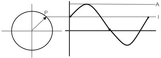
In the above picture, the line A represents the maximum amplitude of the wave form and the line ‘I’ is the magnitude at the point P, of the phasor vector representation. The vector represents the values from 00 to3600 in the axis, at different instances of time.
The vector represents both magnitude and the phase of the waveform. The magnitude is represented along vertical axis and phase of the waveform is represented along with the Horizontal axis. The phase of a waveform may be represented in either degrees or radians.
Phase Difference
When we are analysing two wave forms or two characteristics of a single wave form, then we compare these two wave forms in same coordinate plane. Then we need to analyze each wave form at each position. For example, while comparing the voltage and current of a wave form, we represent them with the same axis, as shown below.
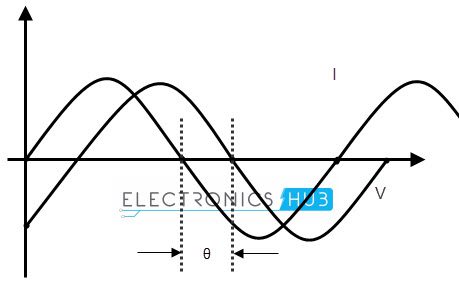
Assume a circuit with voltage and current, for our analysis. Here, the wave ‘I’ represents the current characteristics and wave ‘v’ represents the voltage characteristics of the wave. The phase difference of the 2 waveforms is shown as “θ”. The current wave leads by the voltage wave with a phase difference of θ. The equations for expressing the voltage and current mathematically are given below.
Vt = Vm sin (ωt)
It = Im sin (ωt – Φ)
Where Vm is maximum voltage and Φ is the phase angle.
Phasor Diagram of Sinusoidal Waveform
To draw the phasor diagrams we should follow some rules that the phasor vector always rotates in clock wise direction and the zero phase of the waveform is represented on the positive X axis.
The phasor diagram corresponds to both phase and magnitude of the wave form. We represent the time period or phase angle on X axis and magnitude on Y axis. The length of phasor vector is proportional to voltage or current values at any instance of time.
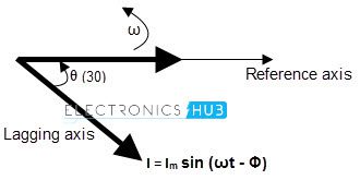
As we already know that, in case of resistors, there is no phase difference between voltage wave and current wave. But in case of inductors, the current phasor lags voltage phasor by Φ phase angle and these two phasors rotate in anti clock wise direction.
This is because the voltage lags in the direction of negative coordinates. So the phase angle also measured in anti clockwise direction.
If we stop the voltage and current phasors at an angle of 300, then the phasor vectors will look like the picture shown below
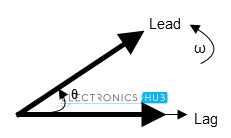
As the two waveforms have same frequency they will maintain the same phase difference all the time. So, even at 300 angle, we can observe that the current phasor lags by the voltage phasor. In other words, voltage phasor leads by current phasor.
But, to say that one phasor is leading and another vector or, lagging another phasor; first we should make one of the 2 phasor vectors as reference. Based on that, we can say the leading or lagging phasor vectors.
Phasor Algebra
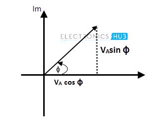
Every phasor has magnitude and angular displacement or phase difference along their X axis and Y axis. If we want to perform mathematical operations like addition or subtraction and multiplication or division, on these phasors, first we need to split the vectors into its vector components, like X component: VA cos ϕ and Y component: VAsin ϕ by using trigonometric basics.
Phasor Addition
To analyze two or more waves, we need to add or subtract the phasors of the waveforms. If we are analyzing the Alternating Current Circuits, the in phased waves do not have any phase difference and the phase difference of out of phased waves is measured in Φ degrees or radians.
Ex: If two voltage waveforms are of 25 volts and 32 volts with same frequency, and assume that they are in- phase. We can add two voltages , to find the sum of the voltages, we get 57 volts.
If the two voltages have different phases, which means when the wave forms are out of phase then we cannot add the them directly to find the overall voltage. This is because, the two wave forms having different directions.
In this case, we can find the total voltage of the AC circuit by adding the two wave forms by vector method. This is called “Vector sum” or “Resultant phasor” by using a trigonometric law called “Parallelogram law”.
Addition of Two Phasors
Let’s see an example to understand about the phasor addition.
Assume that an AC circuit has two voltage waveforms like 20 volts and 30 volts, say V1 and V2 respectively. If the voltage wave V1 leads V2 by 600 phase. Let’s find the total voltage of the AC circuit by phasor addition or vector addition method.
First we should draw the phasor vector diagram with the two voltage vectors, a parallelogram. As shown below.
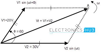
After this, find the voltage sum in normal addition method like V1 + V2 and then find the length of the diagonal. This is called “Resultant vector” or ‘r vector’. This resultant vector is represented by ‘VT’. It is drawn from the origin (zero) to the poi (point of intersection) of the two voltage phasors, say OA.
Though the graphical method of the phasor addition gives us the accurate results about the circuit, it is very time taking to draw and scale all the voltage vectors to the scale. If these phasors are not drawn accurately, we may get the erroneous report of the AC circuit. Then we should follow the analytical method.
In phasor addition method, we should add the voltage phasors in the consideration of their vertical and horizontal directions. The method of using the sine components and cosine components is called “Rectangular form method”.
In this method, the phasor complex number Z = a ± by is divided into two parts, one is imaginary part and the other is real part.
Definition of a Complex Sinusoid
The magnitude of the voltage in analytical method is given as
Vm = cos (Φ) + j Vm (sin Φ)
The vector addition is given below.
If the first vector is V1 = a + jb and the second vector is V2 = x + jy; then the resultant vector sum is given as
Vr = V1 + V2 = (a + x) + j (b + y)
Phasor Addition Using Rectangular Form
The voltage of second vector is 30 volts in the horizontal direction and 0 in vertical direction. So its real part and imaginary parts can be explained as
Horizontal Component = 30 cos 00 = 30 volts
Vertical Component = 30 sin00 = 0 volts
So the voltage V2 in complex form is V2 = 30 + j0
Similarly, the voltage of second vector is 20 volts in the horizontal direction and as it leads voltage by 600 in vertical direction. So its real part and imaginary parts can be explained as
Horizontal Component = 20 cos 600 = 20 x 0.5 = 10 volts
Vertical Component = 20 sin 600 = 20 x 0.866 = 17.32 volts
So the voltage V1 in complex form is V1 = 10 + j17.32
The resultant voltage, VT can be calculated by adding the horizontal and vertical components. That is
VHorizontal = sum of real parts of V1 and V2 = 30 + 10 = 40 volts
VVertical = sum of imaginary parts of V1 and V2 = 0 + 17.32 = 17.32 volts
Now, the magnitude of the resultant vector VT can be calculated by using Pythagoras’s Theorem for triangle.
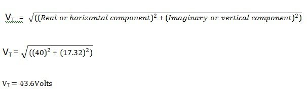
The resultant vector VT is shown in the below given figure.

Phasor Subtraction
As we said earlier, we can do all mathematical operations like addition, subtraction and multiplication, division etc. We learned how to add two phasors and finding resultant vector. Now let’s have a look at subtraction of two phasors.
Phasor or phasor vector subtraction is very much similar to the addition of vectors. In vector subtraction, the difference of the two vectors V1 and V2 is the diagonal of the parallelogram. It is shown in figure.
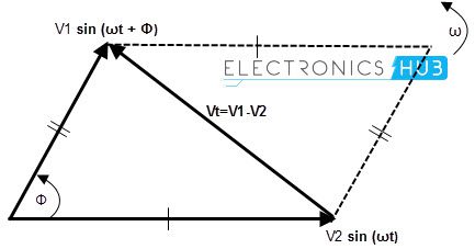
The vector subtraction is given below.
If the first vector is V1 = a + jb and the second vector is V2 = x + jy; then the resultant vector difference is given as
Vr = V1 + V2 = (a + x) – j (b + y)
3 Phase Phasor Representation
We have learned about the single phase AC coil generated sine waves, i.e. single phase sine waves. Now there is another phase which we use most in power transmission in electronics. That is “Three phase”. We generally come across this word in our regular life many times. Now let’s see what actually 3 phase means?
- In single phase, only one coil or wire will rotate in magnetic field, but in three phase there will be three shafts rotating in magnetic field which are at an angle of 1200 to each other, and are connected to same shaft.
- These 3 coils will have the same number of coli turns. So we can say, the current generated by the three coils connected to the single (same) rotor, separated by an angle of 1200 is called “3 phase current”.
- The 3 phase voltage supply will have 3 individual sine wave voltages with equal frequency and magnitude (amplitude) with different phases. To understand and identify the 3 phase concept easily, we represent the three phasors with different colours.
- As single phase phasors, the three phase phasors also rotate in counter clock wise direction with the angular velocity, ω radians / sec.
The 3 phase balanced phasor in delta connection is shown below.
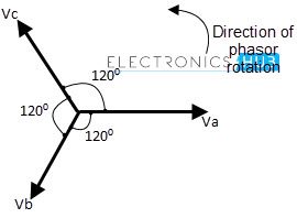
Requirements for 3 Phase Balanced System
To set the 3 phase system in balance, we should set the 3 sine waves according to the conditions listed below.
I. All the 3 variables should have the same amplitude.
II. All the 3 variables should have the same amplitude.
III. All the 3 variables should be separated in a phase of 1200.
The 3 phase sine wave representation is shown in below figure.
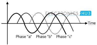
From the above figure, we can say that, the wave form with phase ‘a’ (in blue colour) is out of phase with the wave form of phase ‘b’ (in violet colour) and this wave form is out of phase with the third waveform of phase ‘c’ (in green colour).
The phase difference between these three waveforms is 1200. These wave forms may represent current or voltages of the AC circuit.
3 Phase Voltage Equations
The voltages of the three wave forms are represented as
Va = √2Vm cos ( ωt + Φ )
Vb = √2Vm cos ( ωt + Φ – 1200 )
Vc = √2Vm cos (ωt + Φ- 2400 ) = √2Vm cos ( ωt + Φ +1200 )
Simply, we can say that, the phase “b” follows 1200 behind “a” and phase “c” follows 1200 behind phase “b”.
Summary
Let’s summarize the concept, phasor diagrams and phasor algebra.
- The complex number in the polar form is a “Phasor”. The magnitude is represented along Y axis and with real number; the time period or phase is represented on X axis and with imaginary number.
- The phasors always rotate in counter clock wise direction.
- The phasors can represent two or more sinusoidal quantities at any instant of time, in both magnitude and time period, in their direction of rotation.
- The length of phasor vector represents the RMS velocity of the wave form.
- We use phasors to represent the phase of voltage, current waveforms and to analyze the circuit.
- Phasor are vector quantities which apt for sine waves only.
- In any phasor diagram, the represented wave forms should have same frequency and same amplitude.
- If the phase difference between the wave forms is zero, then the wave forms are said to be “In phase”.
- If the wave forms have the phase difference between them, as Φ; they are said to be “Out of phase”.
- We can perform all types of mathematical operations with the phasor vectors, by finding the resultant vector of the given vectors.
- The vector obtained by adding or subtracting of two vectors is called “Resultant vector”. It is represented by “Vr”.
- In vector addition, the resultant vector is given as Vr = V1 + V2 = (a + x) + j (b + y)
- In vector subtraction, the resultant vector is given as Vr = V1 + V2 = (a + x) – j (b + y)
- The 3 phase vector representation will have 3 phasors, representing the 3 rotating coils of the same conductor.
- In a 3 phase system, the three vectors (wave forms) will be separated to each other by a phase of 1200.
