In this tutorial, we will learn about Passive Low Pass RC Filters. As the name suggests, it is a Low Pass filter designed using Passive Components. In the following sections, you can learn about the basic circuit of Passive Low Pass RC Filters, its frequency response, output voltage, applications and many more.
To get information on Passive High Pass RC Filters, do read the tutorial “Passive High Pass RC Filters“.
Introduction
Filter is a circuit which is used to filter the signals that is it will pass only required signals and avoid unwanted signals. Generally filters are designed by either passive components or active components.
- Passive components are resistors, inductors and capacitors.
- Active components are transistors, FETs and Op-amps.
Low Pass Filter is a filter which will pass only low frequency signals and attenuate or stop high frequency signals. It allows signals only from 0Hz to cut off frequency ‘fc’. This cut off frequency value will depends on the value of the components used in the circuit.
Generally these filters are preferable below the frequency 100 kHz. The cut off frequency is also called as break frequency or turn over frequency.
Passive Low Pass Filter
A Low Pass Filter circuit which is designed by passive components is referred as passive low pass filter.
The following image shows a simple circuit of RC Low Pass Filter is shown below.
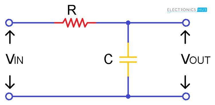
Simply by connecting resistor ‘R’ in series with a capacitor ‘C’ gives RC Low Pass Filter. It can be just referred as Low Pass Filter (LPF). Resistor is independent to the variations of the applied frequencies in the circuit but capacitor is a sensitive component that means it responds to the changes in the circuit.
Since it has only one reactive component this circuit can also termed as ‘one pole filter’ or ‘First order filter’. The input voltage ‘Vin’ is applied in series to the resistor and the output voltage is taken only across the capacitor.
Since capacitor is a sensitive component the main concentration to be observed is about “capacitive reactance”. Capacitive reactance is the opposition response created due to the capacitor in the circuit.
In order to maintain the capacitance of the capacitor, the capacitor will oppose a small amount of current flow in the circuit. This opposition to the current flow in the circuit is called impedance. Thus the capacitive reactance decreases with increase of opposing current.
By this we can say that the capacitive reactance is inversely proportional to the frequency applied to the circuit. The resistive value of the resistor is stable whereas the capacitive reactance value varies. The voltage drop across the capacitor is very less when compared with the voltage potential of the capacitor.
This means at low frequencies the voltage drop is small and the voltage potential is large but at high frequencies the voltage drop is very high and the voltage potential is less. By this phenomenon we can say that the above circuit can acts as a ‘frequency variable voltage divider’ circuit.
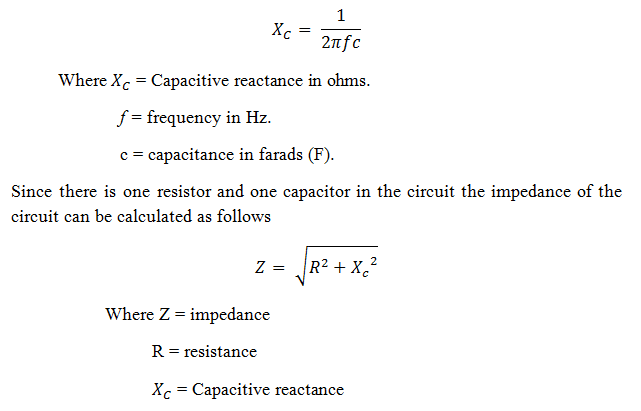
The capacitive reactance can be formulated as follows:
Output Voltage Calculation
In order to get the potential divider equation we have to consider impedance, capacitive reactance, input voltage and output voltage. By using these terms we can formulate the equation for RC potential divider equation as follows:
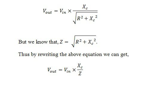 By using this equation we can calculate the value of the output at any applied frequency.
Low Pass Filter Example
Let us examine these output voltage values and capacitive reactance values by considering the resistor and capacitor values. Let the value of the resistor R is 4.7 kΩ and capacitor value as 47 nF. The input A.C voltage supplied is 10V. The frequency values for which we are going to calculate are at 1 kHz and 10 kHz.
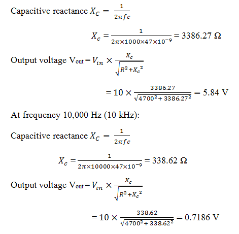
By this we can clearly say that when frequency increases the capacitive reactance decreases. Not only the capacitive reactance but also the output voltage decreases.
From the above example it is observed that the capacitive reactance is decreased from 3386.27 ohms to 338.62 ohms, whereas the output voltage decreased from 5.84 volts to 0.718 volts with the increase of the frequency from 1 kHz to 10 kHz.
Frequency Response of Low Pass Filter
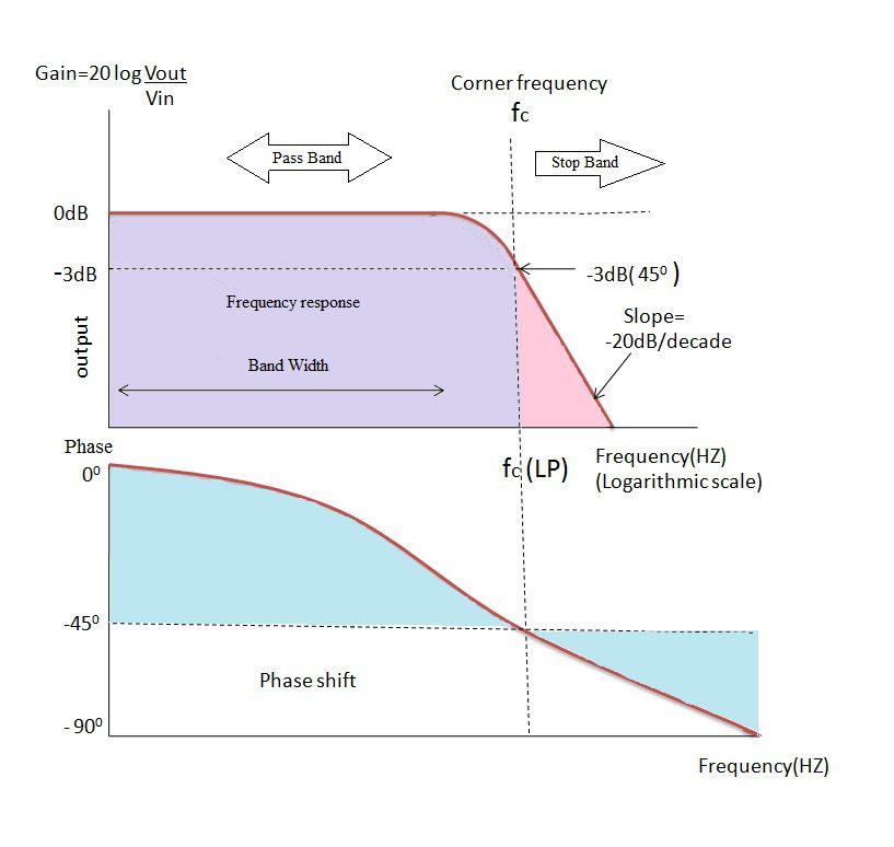
From the introduction to filters we already saw that the magnitude |H(jω)| of the filter is taken as the gain of the circuit. This gain is measured as 20 log (Vout / Vin) and for any RC circuit the angle of the slope ‘roll-off ‘ is at -20 dB/ decade is same.
The band of frequencies below the cut off region is referred as ‘Pass Band’ and the band of frequencies after the cut off frequency are referred as ‘Stop Band’. From the plot it can be observed that the pass band is the Bandwidth of the filter.
From this plot it is clear that until cut off frequency the gain is constantbecause the output voltage is proportional to the frequency value at the low frequencies. This is due to the capacitive reactance which acts like open circuit at low frequencies and allows maximum current through the circuit for high frequencies. The value of the capacitive reactance is very high at low frequencies thus it has greater ability to block the current flow through the circuit.
Once it reaches the cut off frequency value the output voltage decreases gradually and reaches to zero. The gain also decreases along with the output voltage. After the cut off frequency the response of the circuit slope will reaches to roll-off point which occur at -20 dB/ decade.
This is mainly due to the increase of the frequency, when frequency increases the capacitive reactance value decreases and thus the ability to block the current through the capacitor decreases. When current through the circuit increases and due to the limited capacitance of the capacitor the circuit acts as short circuit. Thus the output voltage of filter is zero at high frequencies.
The only way to avoid this problem is to choose the frequency ranges up to which these resistor and capacitor can withstand. The values of the capacitor and the resistor play the major role because on these values only the cut off frequency ‘fc’ will depends. If the frequency ranges are within the cut off frequency range then we can overcome the short circuit problem.
This cut off point will occurs when the resistance value and the capacitive reactance value coincides which means the vector sum of the resistance and reactive capacitance are equal. That is when R = Xc and at this situation the input signal is attenuated by -3dB/decade.
This attenuation is approximately 70.7 % of input signal.The time taken to charge and discharge of the plates of the capacitor varies according to the sine wave. Due to this the phase angle (ø) of the output signal lags behind the input signal after cut-off frequency.At cut-off frequency the output signal is -45° out of phase.
If the input frequency of the filter increases the lagging angle of the circuit output signal increases. Simply for the more frequency value the circuit is more out of phase.
The capacitor has more time to charge and discharge the plates at low frequencies because the switching time of the sine wave is more. But with the increase of frequency the time taken to switch to the next pulse is gradually decreases. Due to this the time variations occurs which leads to phase shift of the output wave.
Cut-off frequency of a passive low pass filter mainly depends on the resistor and capacitor values used in filter the circuit.This cut-off frequencyis inversely proportional to both resistor and capacitor values. The cut-off frequency of a passive low pass filter is given as
fC = 1/(2πRC)
The phase shift of a passive low pass filter is given as
Phase shift (ø) = – tan-1 (2πfRc)
Time Constant (τ)
As we already seen that the time taken by the capacitor for charging and discharging of the plates with respect to the input sinusoidal wave results in the phase difference. The resistor and the capacitor in series connection will produce this charging and discharging effect.
The time constant of a series RC circuit is defined as the time taken by the capacitor to charge up to 63.2% of the final steady state value and also it is defined as the time taken by the capacitor to discharge to 36.8% of steady state value. This Time constant is represented with symbol ‘τ ’.
The relation between the time constant and the cut off frequency is as follows
Time constant τ = RC = 1/ 2πfc and ωc = 1/τ = 1/RC
We can also rewrite in terms cut off frequency as
By this we can say that the output of the filter depends on the frequencies applied at the input and on the time constant.
Passive Low Pass Filter Example 2
Let us calculate the cut off frequency of a low pass filter which has resistance of 4.7k and capacitance of 47nF.
We know that the equation for the cut off frequency is
fc = 1/2πRC = 1/(2π x 4700 x 47 x 10-9) = 720 Hz
Second Order Passive Low Pass Filter
Till now we have studied first order low pass filter which is made by connecting a resistor and capacitor in series. However sometimes a single stage may not enough to remove all unwanted frequencies then second order filter are used as shown below.
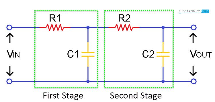
The second order low pass RC filter can be obtained simply by adding one more stage to the first order low pass filter. This filter gives a slope of -40dB/decade or -12dB/octave and a fourth order filter gives a slope of -80dB/octave and so on.
Passive low pass filter Gain at cut-off frequency is given as
A = (1/√2)n
Where n is the order or number of stages
The cut-off frequency of second order low pass filter is given as
fc = 1/ (2π√(R1C1R2C2))
Second order low pass filter -3dB frequency is given as
f (-3dB) = fc √ (2(1/n) – 1)
Where fc is cut-off frequency and n is the number of stages and ƒ-3dB is -3dB pass band frequency.
Low Pass Filter Summary
Low Pass Filter is made up of a resistor and capacitor. Not only capacitor but any reactive component with resistor gives low pass filter. It is a filter which allows only low frequencies and attenuates high frequencies.
The frequencies below the cut off frequency are called as pass band frequencies and the frequencies greater than the cut off frequency are called as stop band frequencies. Pass band is the band width of the filter.
Cut off frequency of the filter will depends on the values of the components chosen for the circuit design. Cut off frequency can be calculated by using the below formula.
fC = 1/(2πRC)
The gain of the filter is taken as magnitude of the filter and the gain can be calculated by using the formula 20 log (Vout / Vin). The output of the filter is constant till the frequency levels reaches to cut off frequency.
At cut-off frequency the output signal is 70.7% of the input signal and after the cut-off frequency output gradually decreases to zero. The phase angle of the output signal lags the input signal after cut-off frequency.
At cut-off frequency the output signal phase shift is 45°.
If we interchange the positions of the resistor and the capacitor in low pass filter circuit then the circuit behaves like high pass filter.
For sinusoidal input waves the circuit behaves like a first order low pass filter. The operation of the first order filter is we have already studied but when the input signal type changes then what happens to the output of the filter have to be observed.
When we change the input signal type to either switch mode (ON/OFF) or else square wave the circuit behaves like an integrator which is discussed as follows.
Low Pass Filter as Wave Shaping Circuit
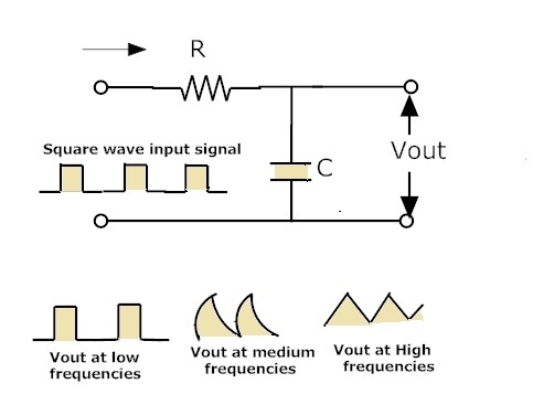
The above figure shows the performance of the filter for square input. When the input of the low pass filter is a square wave then obtained output of the filter will be in triangular form.
This is because the capacitor cannot acts as ON or OFF switch. At low frequencies when the input of the filter is square wave then the output will also be in the square wave only.
When frequency increases then the output of the filter appears like a triangular wave. Still if we increase the frequency then the amplitude of the output signal decreases.
The triangular wave is generated due to the capacitors action or simply charging and discharging pattern of the capacitor leads to triangular wave.
Applications of the Low pass filter
- The main usage of the low pass filter circuits is to avoid A.C. ripples in the rectifier output.
The low pass filter is used in audio amplifier circuits. - By using this passive low pass filter we can directly reduce the high frequency noise to a small disturbance mode in the stereo systems.
- Low Pass filter as integrator can be used as Wave shaping and wave generating circuits because of easy conversion of one type of electrical signal in to another form.
- These are also used at demodulator circuits to extract required parameters from the modulated signals.

2 Responses
How to calculate RC time constant(tau) for second order Low pass filter
How can the filter response of a low pass RC filter circuit be adjusted?