In this tutorial, we will learn the working and implementation of an Operational Amplifier as Differentiator or a Differentiator Amplifier. Differentiator Amplifier can be Passive or Active based on the components used in its design. Configuring Operational Amplifier as Differentiator or Differentiator Amplifier is basically using Op-Amp as a High Pass Filter and is used in wave shaping circuits, frequency modulators etc.
We already discussed about the Operational Amplifier as Integrator in another tutorial, where we learned how to configure an Operational Amplifier as an Integrator. We will do a similar analysis here but this time for Operational Amplifier as Differentiator.
For additional information on High Passive Filters, read “Passive High Pass RC Filters” and “Active High Pass Filter“. You can find the basics of Op-Amp in “Operational Amplifier Basics“.
Op-Amp Differentiator
An op-amp differentiator or a differentiator amplifier is a circuit configuration which is inverse of the integrator circuit. It produces an output signal where the instantaneous amplitude is proportional to the rate of change of the applied input voltage.
Mathematically speaking, the output signal of a Differentiator is the first order derivative of the input signal. For example, if the input signal is a ramp, then the output of the circuit with an Operational Amplifier as Differentiator will be simple DC (as the rate of change of ramp signal is constant). Similarly, if the input signal is a sinusoid, then the output signal is also a sinusoid but with phase difference of 900.
A differentiator with only RC network is called a passive differentiator, whereas a differentiator with active circuit components like transistors and operational amplifiers is called an active differentiator. Active differentiators have higher output voltage and much lower output resistance than simple RC differentiators.
An op-amp differentiator is an inverting amplifier, which uses a capacitor in series with the input voltage. Differentiating circuits are usually designed to respond for triangular and rectangular input waveforms.
Differentiators have frequency limitations while operating on sine wave inputs; the circuit attenuates all low frequency signal components and allows only high frequency components at the output. In other words, the circuit behaves like a high-pass filter.
Ideal Op-Amp Differentiator Circuit
An op-amp differentiating amplifier uses a capacitor in series with the input voltage source, as shown in the figure below.
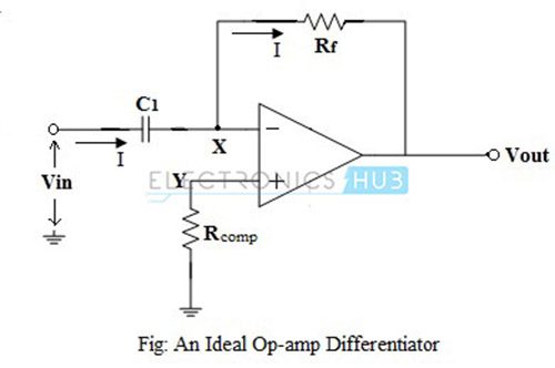
For DC input, the input capacitor C1, after reaching its potential, cannot accept any charge and behaves like an open-circuit. The non-inverting input terminal of the op-amp is connected to ground through a resistor Rcomp, which provides the input bias compensation, and the inverting input terminal is connected to the output through the feedback resistor Rf.
Thus, the circuit behaves like a voltage follower.
When the input is a positive-going voltage, a current I flows into the capacitor C1, as shown in the figure. Since the current flowing into the op-amp’s internal circuit is zero, effectively all of the current I flows through the resistor Rf. The output voltage is,
Vout = – (I * Rf)
Here, this output voltage is directly proportional to the rate of change of the input voltage.
From the figure, node ‘X’ is virtually grounded and node ‘Y’ is also at ground potential i.e., VX = VY = 0 .
From the input side, the current I can be given as:
I = C1 {d(Vin – VX) / dt} = C1 {d(Vin) / dt}
From the output side, the current I is given as:
I = -{(Vout – VX) / Rf} = -{Vout / Rf}
Equating the above two equations of current we get:
C1 {d(Vin) / dt} = -Vout / Rf
Vout = -C1 Rf {d(Vin) / dt}
Above equation indicates that the output is C1 Rf times the differentiation of the input voltage. The product C1 Rf is called as the RC time constant of the differentiator circuit. The negative sign indicates the output is out of phase by 1800 with respect to the input.
The main advantage of such an active differentiating amplifier circuit is the small time constant required for differentiation.
Input and Output Waveforms
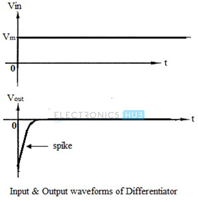
Let us now see the output waveforms for different input signals. When a step input (DC Level) with amplitude Vm is applied to an op-amp differentiator, the output can be mathematically expressed as,
Vout = – C1 Rf {d(Vm) / dt}
For simplicity, assume the product C1 Rf is unity.
Therefore, Vout = 0 , because the amplitude Vm is constant and d(Vm) / dt = 0.
But practically, the output is not zero since the input step wave takes a finite amount of time to rise from 0 volts to Vm volts. Hence, the output appears like a spike at time t = 0, as shown in the figure below.
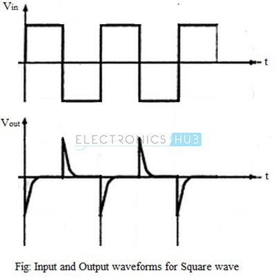
If the input to the differentiator is changed to a square wave, the output will be a waveform consisting of positive and negative spikes, corresponding to the charging and discharging of the capacitor, as shown in the figure below.
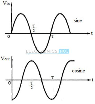
For sine wave input, which is mathematically represented as V (t) = Vm sin ωt, where Vm is the amplitude of the input signal and t is the period, the output of the differentiator is given as,
Vout = – C1 Rf {d(Vm sin ωt) / dt}
For simplicity, let us assume the product C1 Rf is unity.
Vout = – Vm. ω. cos ωt
Thus, the output of a differentiator for a sine wave input is a cosine wave and the input-output waveforms are shown in the figure below.
Frequency Response of Ideal Differentiator
The gain of an op-amp differentiator is directly dependent on the frequency of the input signal. Hence, for DC inputs where f = 0, the output is also zero. As the frequency of the input signal increases, the output also increases. The frequency response of an ideal differentiator is as shown in the figure below.
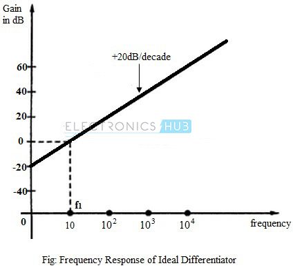
The frequency f1 is the frequency for which the gain of the differentiator becomes unity. It can be seen from the figure that for frequency less than f1, the gain is less than unity. For f1, the gain becomes the unity (0 dB) and beyond f1, the gain increases at 20dB per decade.
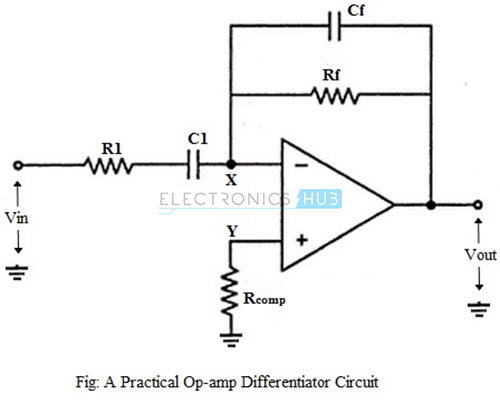
Practical Op-amp Differentiator Circuit
For an ideal differentiator, the gain increases as frequency increases. Thus, at some higher frequencies, the differentiator may become unstable and cause oscillations which results in noise.
These problems can be avoided or corrected in a practical differentiator circuit, which uses a resistor R1 in series with the input capacitor and a capacitor Cf in parallel with the feedback resistor, as shown in the figure below.
The output voltage of the practical op-amp differentiating amplifier circuit is given as,
Vout = – C1 Rf {d(Vin) / dt}
i.e., the output voltage is C1 Rf times the differentiation of the input voltage.
The addition of resistor R1 and capacitor Cf stabilizes the circuit at higher frequencies, and also reduces the effect of noise on the circuit.
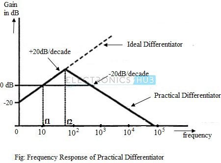
Frequency Response of Practical Differentiator
The gain of the practical differentiator increases with increasing frequency and at a particular frequency, f1, the gain becomes the unity (0 dB). The gain continues to increase at a rate of 20dB per decade till the input frequency reaches a frequency, f2.
Beyond this frequency of the input signal, the gain of the differentiator starts to decrease at a rate of 20dB per decade. This effect is due to the addition of the resistor R1 and capacitor Cf. The frequency response curve of a practical differentiator is as shown in the figure below.
Applications of Op-amp Differentiator
- Differentiating amplifiers are most commonly designed to operate on triangular and rectangular signals.
- Differentiators also find application as wave shaping circuits, to detect high frequency components in the input signal.
Summary of Operational Amplifier as Differentiator
- An op-amp differentiating amplifier is an inverting amplifier circuit configuration, which uses reactive components (usually a capacitor than inductor).
- The differentiator performs mathematical differentiation operation on the input signal with respect to time i.e., the instantaneous output voltage is proportional to the rate of change of the input signal.
- Differentiating circuits are commonly used to operate on triangular and rectangular signals. While operating on sine wave inputs, differentiating circuits have frequency limitations.

5 Responses
good explanation
What is the angle of gain (Vo/Vin)???
good concepts!
are the spikes (output of square wave) in right direction ? are’t these are 180 degree out of phase…!!
Awesome