A simple project on Obstacle Avoiding Robot is designed here. Robotics is an interesting and fast growing field. Being a branch of engineering, the applications of robotics are increasing with the advancement of technology.
The concept of Mobile Robot is fast evolving and the number of mobile robots and their complexities are increasing with different applications.
There are many types of mobile robot navigation techniques like path planning, self – localization and map interpreting. An Obstacle Avoiding Robot is a type of autonomous mobile robot that avoids collision with unexpected obstacles.
Obstacle Avoiding Robot using Arduino
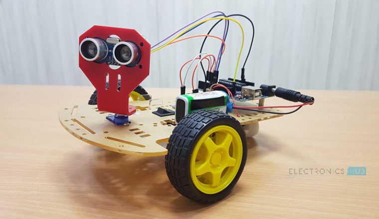
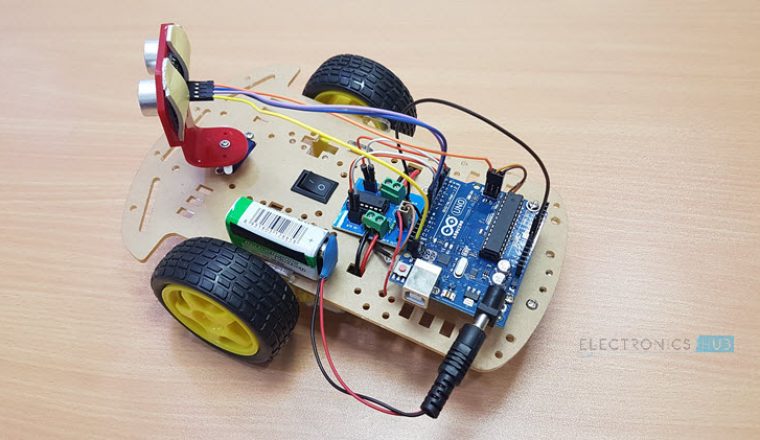
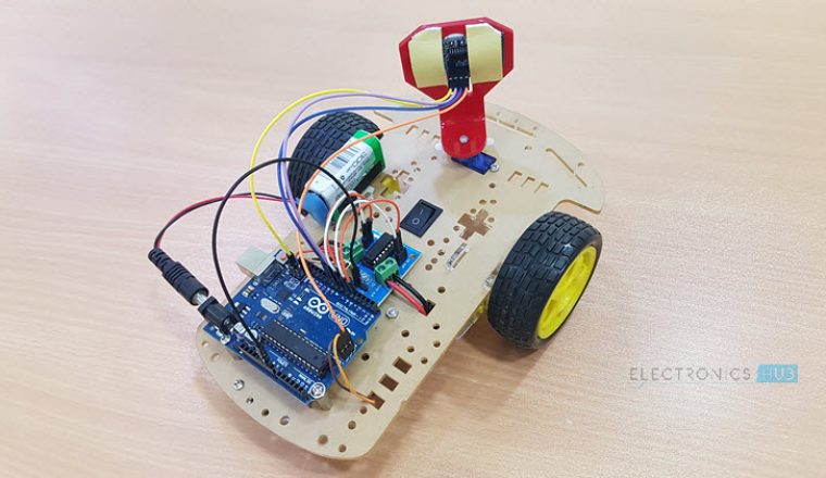
In this project, an Obstacle Avoiding Robot is designed. It is an Arduino based robot that uses Ultrasonic range finder sensors to avoid collisions.
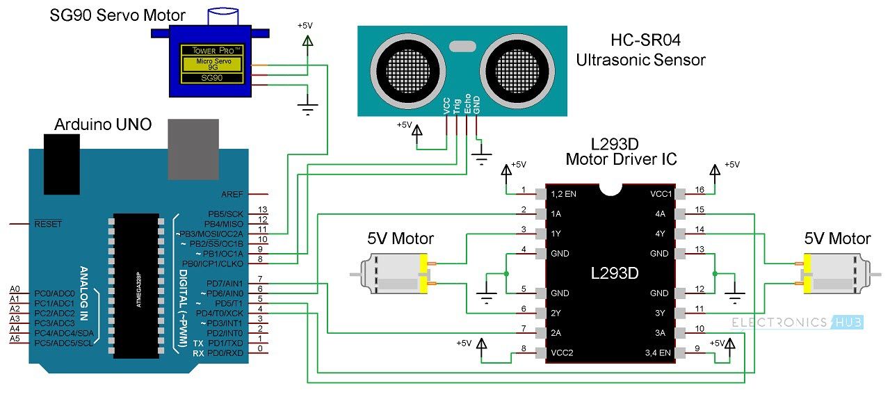
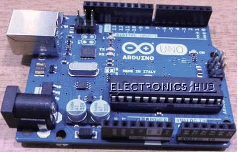
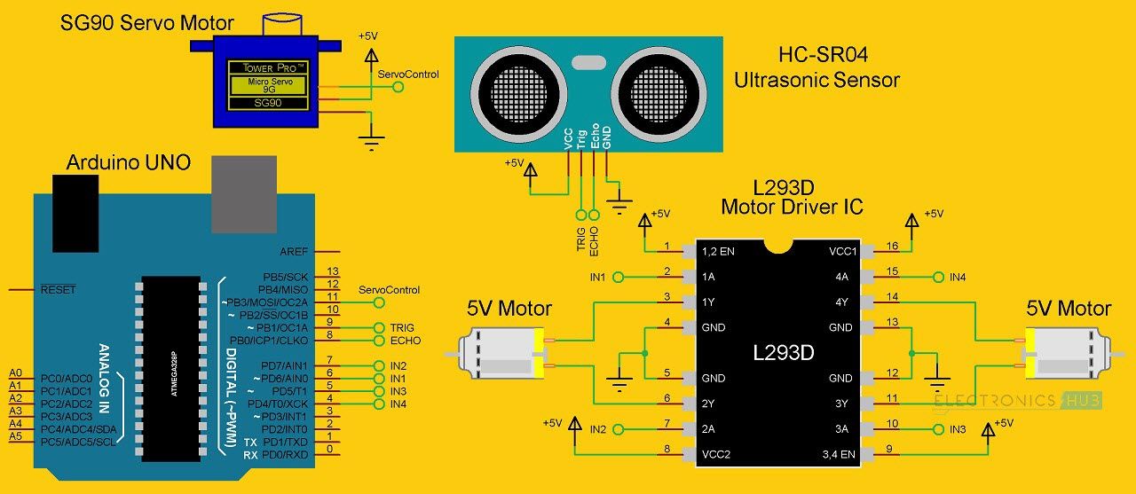
Arduino Uno is an ATmega 328p Microcontroller based prototyping board. It is an open source electronic prototyping platform that can be used with various sensors and actuators. Arduino Uno has 14 digital I/O pins out of which 6 pins are used in this project. It is an Ultrasonic Range Finder Sensor. It is a non-contact based distance measurement system and can measure distance of 2cm to 4m. It is a motor driver which can provide bi-directional drive current for two motors. The Tower Pro SG90 is a simple Servo Motor which can rotate 90 degrees in each direction (approximately 180 degrees in total). Arduino is the main processing unit of the robot. Out of the 14 available digital I/O pins, 7 pins are used in this project design. The ultrasonic sensor has 4 pins: Vcc, Trig, Echo and Gnd. Vcc and Gnd are connected to the +5v and GND pins of the Arduino. Trig (Trigger) is connected to the 9th pin and Echo is connected to 8th pin of the Arduino UNO respectively. A Servo Motor is used to rotate the Ultrasonic Sensor to scan for obstacles. It has three pins namely Control, VCC and GND. The Servo Control Pin is connected to pin 11 of Arduino while the VCC and GND are connected to +5V and GND. L293D is a 16 pin IC. Pins 1 and 9 are the enable pins. These pins are connected to +5V. Pins 2 and 7 are control inputs from microcontroller for first motor. They are connected to pins 6 and 7 of Arduino respectively. Similarly, pins 10 and 15 are control inputs from microcontroller for second motor. They are connected to pins 5 and 4 of Arduino. Pins 4, 5, 12 and 13 of L293D are ground pins and are connected to Gnd. First motor (consider this as the motor for left wheel) is connected across the pins 3 and 6 of L293D. The second motor, which acts as the right wheel motor, is connected to 11 and 14 pins of L293D. The 16th pin of L293D is Vcc1. This is connected to +5V. The 8th pins is Vcc2. This is the motor supply voltage. This can be connected anywhere between 4.7V and 36V. In this project, pin 8 if L293D is connected to +5V supply. NOTE: The power supply to the Motor Driver i.e. Pins 1 (enable 1), 8 (VCC2), 9 (enable 2) and 16 (VCC1) should be given a seperate power supply. Motor Driver boards are available with on – board 5V voltage regulator. A similar one is used in the project. If the above Circuit Diagram of the Obstacle Avoiding Robot is unclear, the following image might be helpful. Before going to working of the project, it is important to understand how the ultrasonic sensor works. The basic principle behind the working of ultrasonic sensor is as follows: Using an external trigger signal, the Trig pin on ultrasonic sensor is made logic high for at least 10µs. A sonic burst from the transmitter module is sent. This consists of 8 pulses of 40KHz. The signals return back after hitting a surface and the receiver detects this signal. The Echo pin is high from the time of sending the signal and receiving it. This time can be converted to distance using appropriate calculations. The aim of this project is to implement an obstacle avoiding robot using ultrasonic sensor and Arduino. All the connections are made as per the circuit diagram. The working of the project is explained below. When the robot is powered on, both the motors of the robot will run normally and the robot moves forward. During this time, the ultrasonic sensor continuously calculate the distance between the robot and the reflective surface. This information is processed by the Arduino. If the distance between the robot and the obstacle is less than 15cm, the Robot stops and scans in left and right directions for new distance using Servo Motor and Ultrasonic Sensor. If the distance towards the left side is more than that of the right side, the robot will prepare for a left turn. But first, it backs up a little bit and then activates the Left Wheel Motor in reversed in direction. Similarly, if the right distance is more than that of the left distance, the Robot prepares right rotation. This process continues forever and the robot keeps on moving without hitting any obstacle. NOTE By the end of this article, you came to know about designing an obstacle avoidance robot and the code to run the device. To your surprise, we have also provided Robot vacuum cleaners that make use of anti-collision and obstacle avoidance sensors. Just with a click, know more about the Robot Vacuum Cleaners that has amazing features. Earlier the robots move in all directions as per the commands are given to it. Later they came to know that it got stuck when there is an unexpected obstacle in front of it. So they made extreme research work and come with the Obstacle avoidance Arduino robots. You came to know about its applications, working, and the hardware parts required assembling. You have attempted it many times and didn’t get the result or would like to get from other sources. Then the Arduino Robot Kits is for you. These kits are a great solution for beginners, and the engineers to build their knowledge in Arduino and Robots by designing cool projects. It has a manual to guide assembling procedure, working theories and project designs. Read the full-length article to know more about the Arduino robot kits. Arduino Robot Kits Related Articles:Circuit Diagram
Hardware Required
Component Description
Arduino Uno
HC – SR04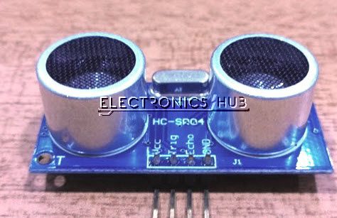
L293D
Servo Motor
Design of Obstacle Avoiding Robot using Arduino
Working
Applications

32 Responses
please I will be glad if I can get the write up (report ) of this project. I find it interesting and I want to embark on it. Pls I will be glad if I can get the material.
thanks in anticipation.
it doesnt work me at all time .i do all my wiring right and the 2 mortor are going to backward
if there is not proper coding, it wont work
Do u have its code?
when the robot stops after it starts working. What to do to stop the robot movement and when it starts to move
The Robot doesn’t stop. It can only be stopped by disconnecting it from the power supply.
You can include a bluetooth module
did everything as you said but motors are not rotating at all
did all the connections but motors are not rotating
Don’t you have any cost analization for this?
Is it only a design of robotic vehicles can be done alone using ultrasonic sensor?
Could you please tell me what program you use to write a circuit diagram?
We are using Proteus.
Hi, where can I find the code source for this project ?
Thanks
Does anyone have the code for this?
What’s the motivation for this?
Can I use ordinary DC motors instead of geared ones?
Yes. You can.
My IC gets very hot in short time and I use 9v battery. If i use 5V then it wont move
What IC gets hot? The Microcontroller or the Motor Driver?
We want code
What is the difference of this with the existing projects
let them struggle
Where is codes?
Want thé code please!!!
Can you send the code of this project?
please I will be happy if I can get the write up (report ) of this project. I find it interesting and I want to embark on it. Pls I will be happy if I can get the material.
thanks you
Hy I want to make smartphone controlled with obstacle avoiding car using nodemcu please help me
How to indicate battery backup in obstacle avoiding car??
How to indicate battery backup in obstacle avoiding robot car?
Can i get the code for this? I am a beginner and i cant wrote a code
Can you help me with it’s coding…