In this tutorial, we will learn about Maximum Power Transfer Theorem (MPTT). It is one of the basic yet important laws that states the necessary condition for maximum power transfer (not to be confused with maximum efficiency).
Maximum Power Transfer Theorem
In any electric circuit, the electrical energy from the power supply is delivered to the load where it is converted into a useful work. Practically, the entire supplied power will not be present at the load due to the heating effect and other constraints in the network. Therefore, there exists a certain difference between drawing and delivering powers.
The size of the load always affects the amount of power transferred from the supply source, i.e., any change in the load resistance results a change in the power transferred to the load. Thus, the Maximum Power Transfer Theorem ensures the ideal condition to transfer the maximum power to the load. Let us see ‘how’.
Maximum Power Transfer Theorem Statement
The Maximum Power Transfer Theorem states that in a linear, bilateral DC network, Maximum Power is delivered to the load when the load resistance is equal to the internal resistance of the source.
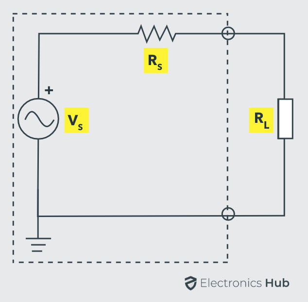
If it is an independent voltage source, then its series resistance (internal resistance RS) or if it is independent current source, then its parallel resistance (internal resistance RS) must equal to the load resistance RL to deliver maximum power to the load.
Proof of Maximum Power Transfer Theorem
The Maximum Power Transfer Theorem ensures the value of the load resistance, at which the maximum power is transferred to the load.
Consider the below DC two terminal network (left side circuit). The condition for maximum power is determined by obtaining the expression of power absorbed by load using mesh or nodal current methods and then deriving the resulting expression with respect to load resistance RL.
This is quite a complex procedure. But in the previous tutorials, we have seen that the complex part of the network can be replaced with a Thevenin’s equivalent as shown below.
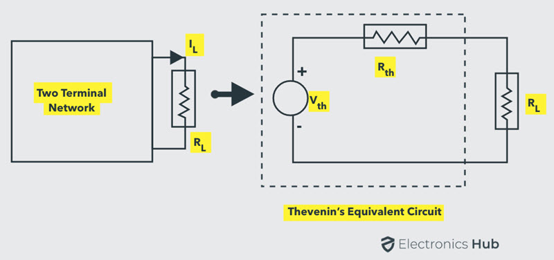
The original two terminal circuit is replaced with a Thevenin’s equivalent circuit across the variable load resistance. The current through the load for any value of load resistance is
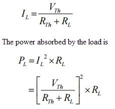
Form the above expression, the power delivered depends on the values of RTH and RL. However, as the Thevenin’s equivalent is a constant, the power delivered from this equivalent source to the load entirely depends on the load resistance RL. To find the exact value of RL, we apply differentiation to PL with respect to RL and equating it to zero as shown below:
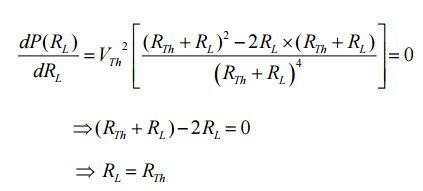
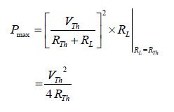
Therefore, this is the condition of matching the load where the maximum power transfer occurs when the load resistance is equal to the Thevenin’s resistance of the circuit. By substituting the RTH = RL in the previous equation, we get:
The maximum power delivered to the load is,
Total power transferred from source is:
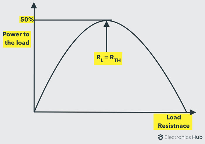
Hence, the maximum power transfer theorem expresses the state at which maximum power is delivered to the load i.e., when the load resistance is equal to the Thevenin’s equivalent resistance of the circuit. Below figure shows a curve of power delivered to the load with respect to the load resistance.
Note that the power delivered is zero when the load resistance is zero as there is no voltage drop across the load during this condition. Also, the power will be maximum, when the load resistance is equal to the internal resistance of the circuit (or Thevenin’s equivalent resistance). Again, the power is zero as the load resistance reaches to infinity as there is no current flow through the load.
Power Transfer Efficiency
We must remember that this theorem states only maximum power transfer but not for maximum efficiency. If the load resistance is smaller than source resistance, power dissipated at the load is reduced while most of the power is dissipated at the source, then the efficiency becomes lower.
Consider the total power delivered from source equation (equation 2), in which the power is dissipated in the equivalent Thevenin’s resistance RTH by the voltage source VTH.
Therefore, the efficiency under the condition of maximum power transfer is:
Efficiency = Output / Input × 100
= IL2 RL / 2 IL2 RL × 100
= 50 %
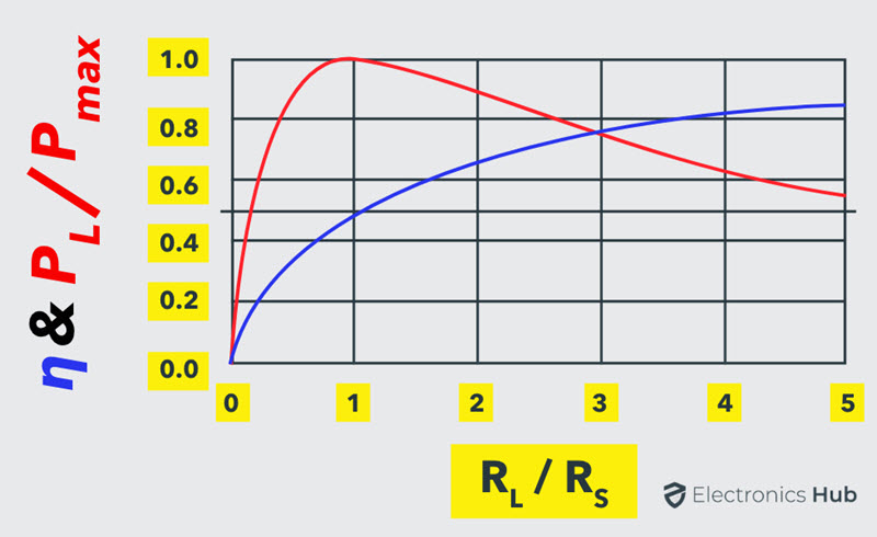
Hence, at the condition of maximum power transfer, the efficiency is 50%, that means only half of the generated power is delivered to the load and at other conditions, a small percentage of power is delivered to the load, as indicated in efficiency verses maximum power transfer the curves below.
For some applications, it is desirable to transfer maximum power to the load than achieving high efficiency such as in amplifiers and communication circuits.
On the other hand, it is desirable to achieve higher efficiency than maximized power transfer in case of power transmission systems, where a large load resistance (much larger value than internal source resistance) is placed across the load. Even though the efficiency is high the power delivered will be less in those cases.
Maximum Power Transfer Theorem for AC Circuits
In an active network, it can be stated that the maximum power is transferred to the load when the load impedance is equal to the complex conjugate of an equivalent impedance of a given network as viewed from the load terminals.
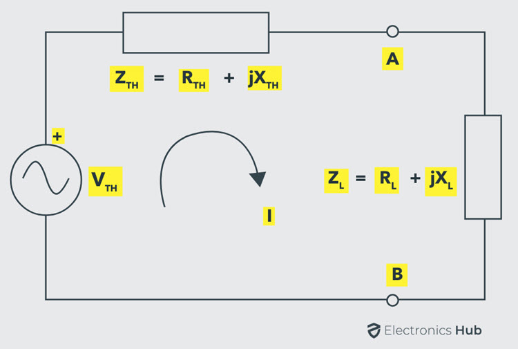
Consider the above Thevenin’s equivalent circuit across the load terminals in which the current flowing through the circuit is given as:
The power delivered to the load,
For maximum power the derivative of the above equation must be zero, after simplification we get
Putting the above relation in equation 1, we get
This maximum power transferred, PMAX = V2TH / 4 RTH or V2TH/ 4 RL
Applying Maximum Power Transfer Example to DC Circuit
Consider the below circuit to which we determine the value of the load resistance that receives the maximum power from the supply source and the maximum power under the maximum power transfer condition.
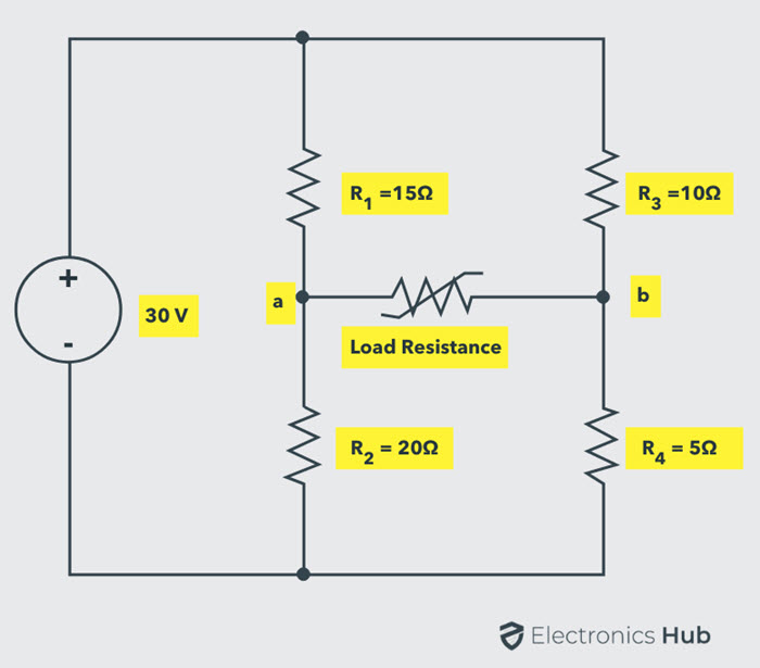
Disconnect the load resistance from the load terminals ‘a ‘and ‘b’. To represent the given circuit as Thevenin’s equivalent, we have to determine the Thevenin’s voltage VTH and Thevenin’s equivalent resistance RTH.
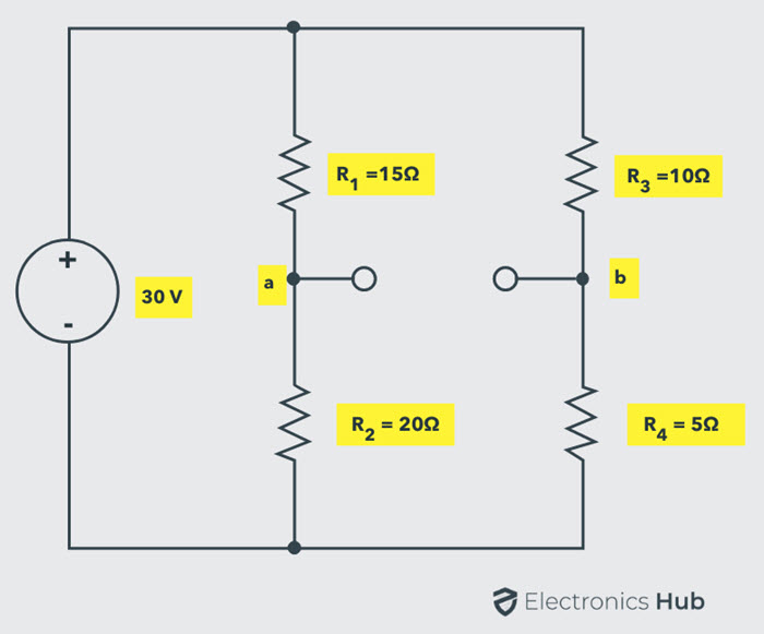
The Thevenin’s voltage or voltage across the terminals ab is Vab = Va – Vb
Va = V × R2 / (R1 + R2)
= 30 × 20 /×(20 + 15)
= 17.14 V
Vb = V × R4/ (R3 + R4)
= 30 × 5 /(10 + 5)
= 10 V
Vab = 17.14 – 10
= 7.14 V
VTH = Vab = 7.14 Volts
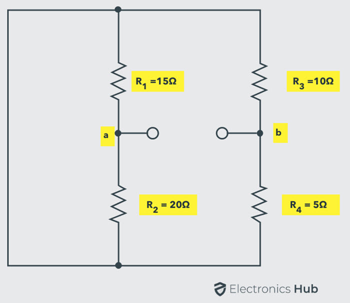
Calculate the Thevenin’s equivalent resistance RTH by replacing sources with their internal resistances (here, let us assume that voltage source has zero internal resistance so it becomes a short circuit).
Thevenin’s equivalent resistance or resistance across the terminals ab is
RTH = Rab = [R1R2 / (R1 + R2)] + [R3R4 /(R3 + R4)]
= [(15 × 20) / (15 + 20)] + [(10 × 5) / (10+ 5)]
= 8.57 + 3.33
RTH = 11.90 Ohms
The Thevenin’s equivalent circuit with above calculated values by reconnecting the load resistance is shown below.
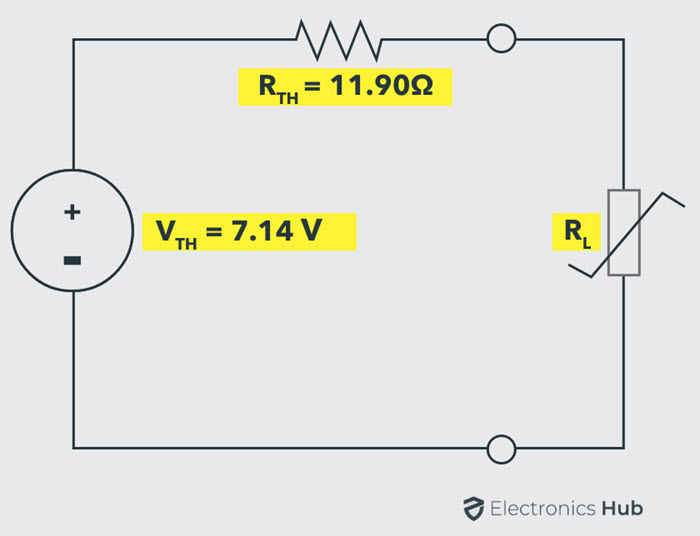
From the maximum power transfer theorem, RL value must equal to the RTH to deliver the maximum power to the load.
Therefore, RL = RTH= 11.90 Ohms
And the maximum power transferred under this condition is,
PMAX = V2TH / 4 RTH
= (7.14)2 / (4 × 11.90)
= 50.97 / 47.6
= 1.07 Watts
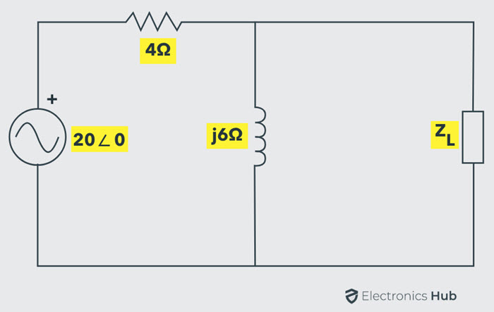
Applying Maximum Power Transfer to AC circuit
The below AC network consists of load impedance ZL of which both reactive and resistive parts can be varied. Hence, we have to determine the load impedance value at which the maximum power delivered from the source and also the value of the maximum power.
To find the value of load impedance, first, we find the Thevenin’s equivalent circuit across the load terminals. For finding Thevenin’s voltage, disconnect the load impedance as shown in below figure.
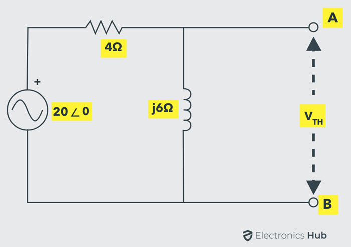
By voltage divider rule,
VTH = 20∠0 × [j6 / (4 + j6)]
= 20∠0 ×[6∠90 / 7.21∠56.3]
= 20∠0 × 0.825∠33.7
VTH = 16.5∠33.7 V
By shorting the voltage source, we calculate the Thevenin’s equivalent impedance of the circuit as shown in figure.
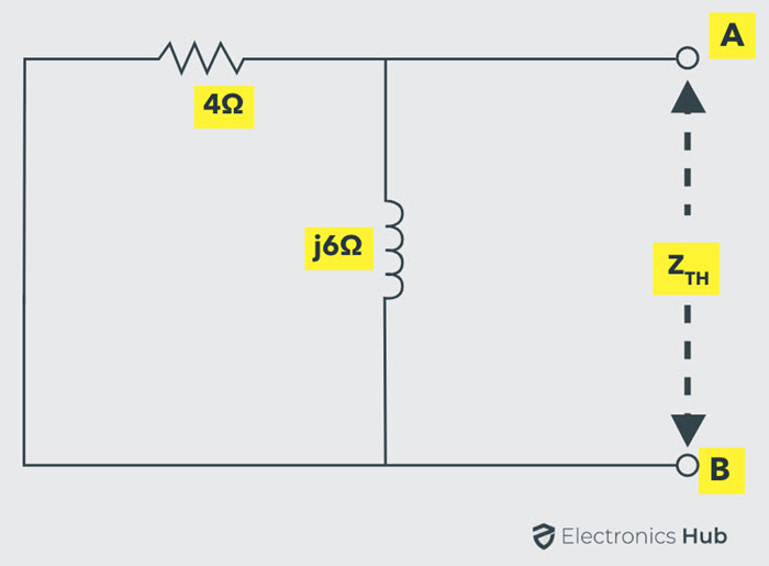
Therefore,
ZTH = (4 × j6) / (4 + j6)
= (4 × 6∠90) / (7.21∠56.3)
= 3.33∠33.7 0r 2.77 + j1.85 Ohms
Hence, the Thevenin’s equivalent circuit across the load terminals is shown in below.
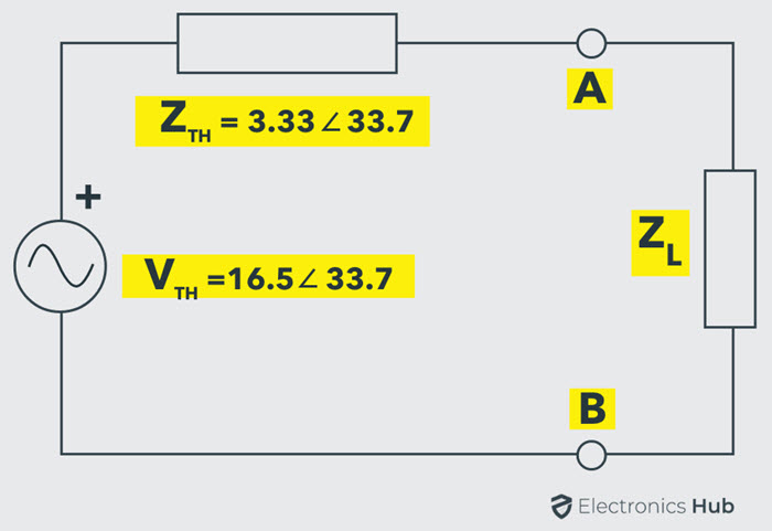
Therefore to transfer the maximum power to the load, the value of the load impedance should be
ZL = ZTH
= 2.77 – j1.85 ohms
The maximum power delivered, PMAX
= V2TH / 4 RTH
= (16.5)2/4(2.77)
= 272.25 / 11.08
= 24.5 W
Practical Application of Maximum Power Transfer Theorem
Consider the practical example of a speaker with an impedance of 8 ohms. It is driven by an audio amplifier with an internal impedance of 500 ohms. The Thevenin’s equivalent circuit is also shown in figure.
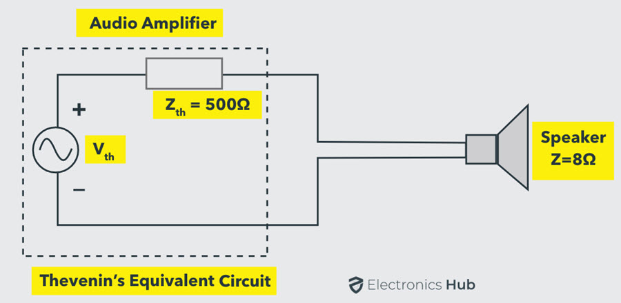
According to the maximum power transfer theorem, the power is maximized at the load if the load impedance is 500 ohms (same as internal impedance). Or else internal resistance has to be changed to 8 ohms to achieve the Maximum Power Transfer condition. However, it is not possible to change either of them.
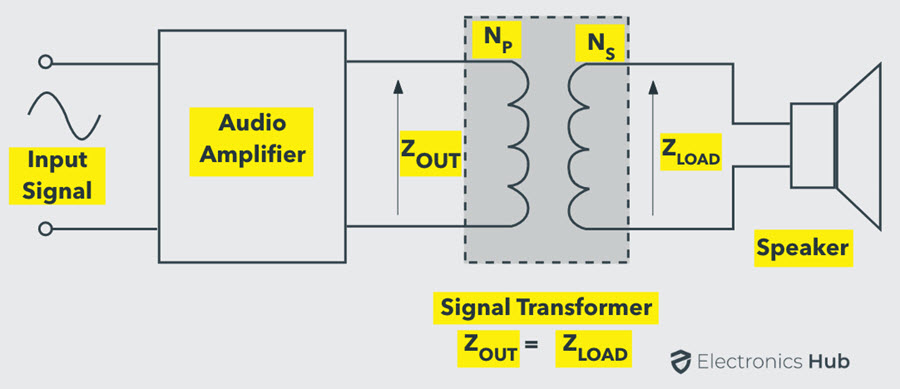
So, it is an impedance mismatch condition and it can be overcome by using an impedance matching transformer with its impedance transformation ratio of 500:8.

2 Responses
It helped me
That makes me understand this concept. thanks 👍