Laser based Security System is a type of security and alarm system that uses laser light and a light sensor. A security system protects our homes, offices, banks, lockers etc. from intrusion and unauthorised access. There are different types of security systems available and laser based security system is an important and efficient type.
A Laser security system can acts as a standalone system, which makes some sound or noise when it detects any irregular activity, or can be part of a much bigger security and home automation system, which can send messages, call the owner etc.
In this project, we have designed a simple DIY lased based security system, which acts as a tripwire like security system and triggers an alarm when the laser in interrupted.
WARNING: We have used a laser pointer in this project. Direct exposure of laser light on eyes can be very dangerous. Even though it is a low power laser, avoid direct eye exposure of laser.
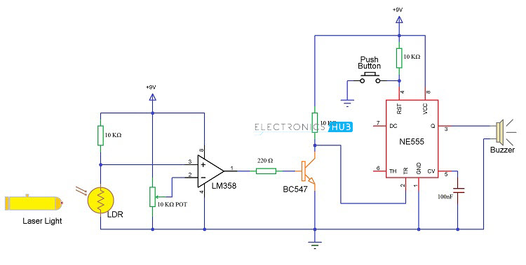
Circuit Diagram
Components Required
- LM358 (Op – Amp IC)
- NE555 (Timer IC)
- LDR
- 3 x 10 KΩ Resistors (1/4 Watt)
- 220 Ω Resistors (1/4 Watt)
- 10 KΩ Potentiometer
- BC547 (NPN Transistor)
- Small Buzzer
- 100 nF Capacitor (Ceramic Disc Type Capacitor – Code 104)
- Push Button
- Laser Pointer
- 9V Battery
- Connecting Wires
- Breadboard (Prototyping board)
Component Description
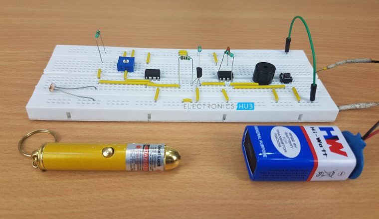
Laser Pointer
Laser Pointer acts as the main source of light in this project. We have used a small laser pointer with an output power of less than 1mW. The laser pointer emits red light and the wavelength of the laser output is between 630 nm to 680 nm.

LDR (Light Dependent Resistor)
The LDR acts as a light sensor in this project. As the intensity of the light falling on the LDR increases, the resistance of the LDR decreases and vice – versa. The LDR is used in combination with the laser to form the light sensor and source.
NE555 (IC 555)
IC 555 is a precision timing IC that provides time delays or oscillations. 555 Timer IC has three modes of operation: Astable, Monostable and Bi-stable. In this project, we are going to use the IC 555 in Bi-stable mode.
LM358 (OP – Amp)
LM358 is a dual Operational Amplifier IC and it is capable of operating in all the conventional operational amplifier circuits. In this project, the LM358 is used as a Comparator.
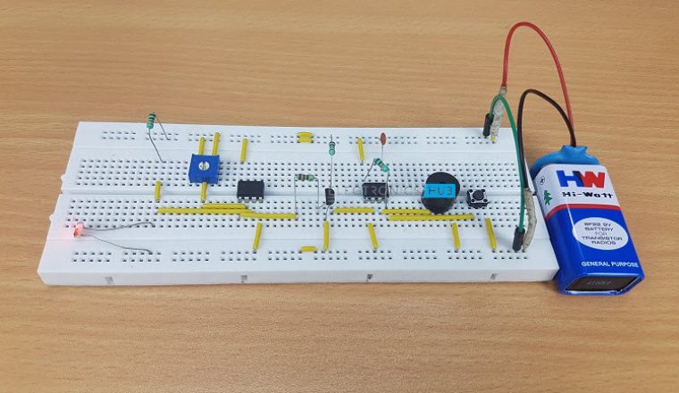
Circuit Design
The design of the laser security system circuit is very simple. We will see the design of the circuit in this section and in the working explanation we will see the working of the individual component.
Coming to the design of the circuit, first, the LDR and a 10 K Ω resistor are connected in a voltage divider fashion and its output (common point) is connected to the pin 3 (non – inverting) of the Op- Amp IC LM358.
For the inverting terminal (pin 2), connect the wiper of a 10 KΩ potentiometer (other two terminal of the POT are connected to VCC and GND).
The output of the Op – Amp (Pin 1) is connected to the base of the transistor (BC547) through a resistor.
The trigger pin of 555 (Pin 2) is pulled high using a 10 KΩ resistor.
The reset pin (pin 4) of the 555 is connected to VCC through a 10 KΩ resistor and a push button is connected between Pin 4 of 555 and GND. A bypass capacitor of 100 nF is connected between pins 5 and GND. A buzzer is connected to pin 3 of 555 IC.
Rest of the connection are shown in the circuit diagram.
Working of the Project
A simple, cheap and effective laser based security system is developed in this project. Let us see the working of this project.
First, the Op – Amp circuit acts as a comparator i.e. it compares the voltages at the inverting and non – inverting terminals and produces an output accordingly.
The LDR – 10 KΩ resistor Voltage divider is connected to the non – inverting terminal of Op –Amp and a POT is connected to the inverting terminal.
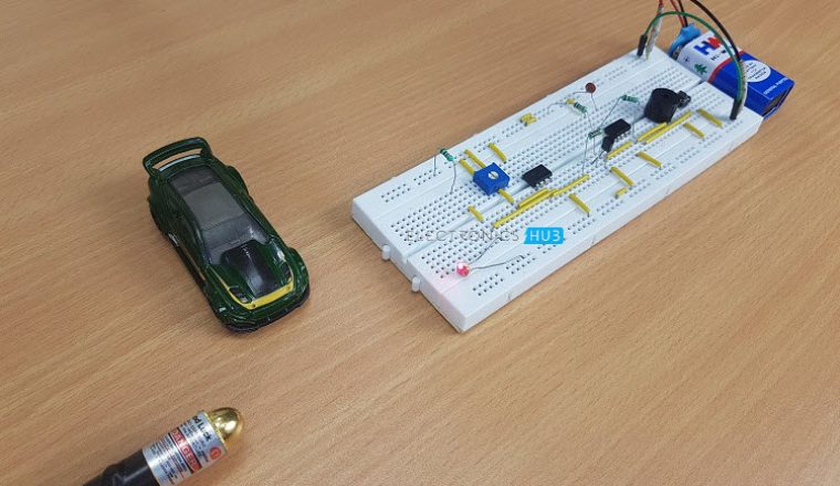
Assume, the laser pointer is placed directly in line of sight to the LDR and the light from the laser is continuously being incident on LDR.
In this situation, the resistance of LDR falls down to few Ohms (or tens of Ohms) and as a result, the voltage at the non – inverting terminal will be less than that at the inverting voltage. The output of the Op –Amp is low and the transistor is OFF.
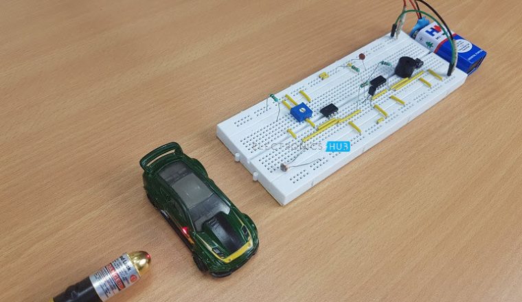
If the laser light is blocked by an intruder from falling on the LDR (even for a small duration), the resistance of the LDR goes to few hundreds of Ohms and as a result, the output of the Op –Amp will be HIGH. This will turn on the Transistor.
As the output of the transistor is connected to the Trigger Pin (Pin 2) of the 555 Timer IC, if the transistor is ON, the trigger pin gets a short low pulse and as a result, the output of the 555 becomes HIGH. This will activate the alarm by turning ON the buzzer.
Since, the 555 Timer IC is configured as a Bi – Stable Multivibrator, a small active low trigger pulse at the trigger pin will set its output to HIGH and in order to reset it we need to push the reset button.
Until the reset push button is pushed, the alarm will stay on hence, we can place the reset button at a secret location so that only the owner can disable the alarm.
Advantages
- The circuit, construction and setup for the Laser Security System is very simple.
- If used with a battery, the laser security system can work even when there is a power outage.
Disadvantages
- The laser security system works only if the laser is obstructed. If the intruder passes without obstructing the laser, it is considered as a failure.
- In order to secure a larger area, we need more lasers and corresponding sensors.
Applications
- Laser Security System can be used in safety lockers in our homes, where even if the locker’s code is hacked, it acts as an additional layer of security.
- Apart from security systems, this laser based setup can also be used to check if pets or babies crossed a certain boundary.

41 Responses
i followd your project but in my case buzzer is not off when i connect battry it sounds on and no effect of laser on the circuit and ldr awhy
I am having the same problem! Somebody please help.
set potetiometer it will rotate sowley anti clockwise then check it again
yesss same problem facing plzzz guide me
try changing the LEd
sir plz help me its not working the buzzer doesnot stops when laser falls on LDR
Nice
Let it completely fall on the LDR. Then it would work.
Your project is really wonderful. But i have a question. Can i use Arduino board instead of NE555 IC?
Of course you can use Arduino. All you need to do is to read for the HIGH and LOw outputs from the Op-Amp and program the Arduino accordingly.
Sorry, the buzzer always remains on, whether the laser falls on it or not… Please help me.
Facing same problem any solution ….
This project is very wonderfull
.but i have a one question on that project
WHAT QUESTION?
Without using ic555,can run the project
You can use Arduino, if you are interested in a little bit programming.
Cover LDR by folding paper. Or buy ldr cap
It works thanks!!
wow magic!!!!
Great circuit, thanks.
You can add a second laser to the LM358. Also you will need a second LDR and it has to be the same.
1. Connect the same POT middle connector to the Inverting Input B ( terminal 6)
2. Connect LDR through the same 10K resistor.
3.Connect LDR to the Non-Inverting Input B (terminal 5)
4. Connect the LM358 Output B ( terminal7) to the same 220k resistor.
Apply the same amount of light on both LDR
can somebody please help! how do we choose the values of the resistors and the capacitor? somebody show me how the values are derived please!
I did this project but its not working without detecting the obstacle buzzer is continuously on.pls help me it’s my mini project
mine is not working , plz help me sir.
What error are you getting?
MINE TOO
the buzzer will still beeping even though it does not contact with laser
Try to adjust the POT and set it just before the buzzer is turned ON.
can you explain it further sir?
This is urgent. I need to know how long the alarm goes off for and based on what? if there are any sort of formulas that can explain that please let me know! thanks.
The alarm shall be ON till 1) the switch is pressed or 2) the battery is drained assuming that the rest of the circuit is working fine.
in above diagram of 555 what Q indicate ?
Q is output of 555 IC.
Very good project it is working!
Reset button is not working ..
Help please
Output of 555 is high but the buzzer is not beeping…plz help me
Sorry, the buzzer always remains on, whether the laser falls on it or not… Please help me.
its working …and this project is just amazing ..
i have to thank my physics sir ..who have done a great role in this project..
thanks a lot..
Mine circuit is not getting reset when laser is interrupted
Buzzer is continuous on when battery is connected
Hey , I don’t have small 10k pot of trim pot , can I use 10k pot ( shaft one)? If yes how?
Also can I use BC 147 transistor instead of BC 547
Got the output…thank u so much sir..i have done this as my mini project.🤩