Infrared (IR) communication is a very common wireless communication technology. IR communication is an easy to use and inexpensive wireless communication. IR Communication generally comprises of IR Transmitter and Receiver.
The most common use of Infrared (IR) communication is remote controls of different appliances like TV’s. The handheld remote control of the TV consists of IR Transmitter and the IR Receiver is placed at the TV.
Some embedded projects also consists of IR Transmitter and Receiver Modules where they can be used as proximity sensors or distance measurement sensors.
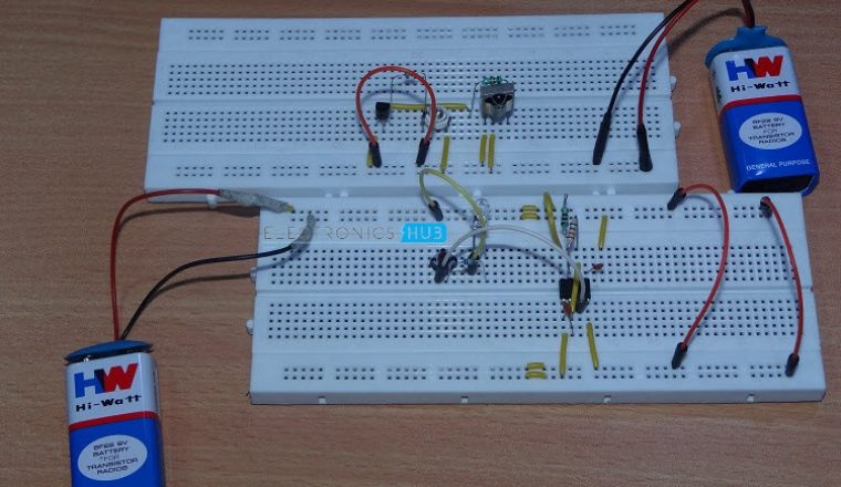
In this project, we have demonstrated the functioning of a simple IR Transmitter and Receiver using 555 Timer.
IR Transmitter and Receiver Circuits
The aim of the project is to explain how Infrared (IR) communication works with the help of simple hardware. For this project, we have used TSOP 1738 IR Receiver to receive infrared signals and a simple IR LED to transmit infrared signals. The circuit diagram, components and the working is explained in the subsequent sections.
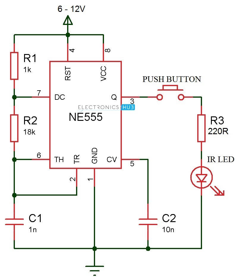
IR Transmitter and Receiver Circuit Diagram
The IR Transmitter and Receiver circuit diagram is shown in the following images. The circuit is divided in to IR Transmitter circuit and IR Receiver circuit.
IR Transmitter Circuit

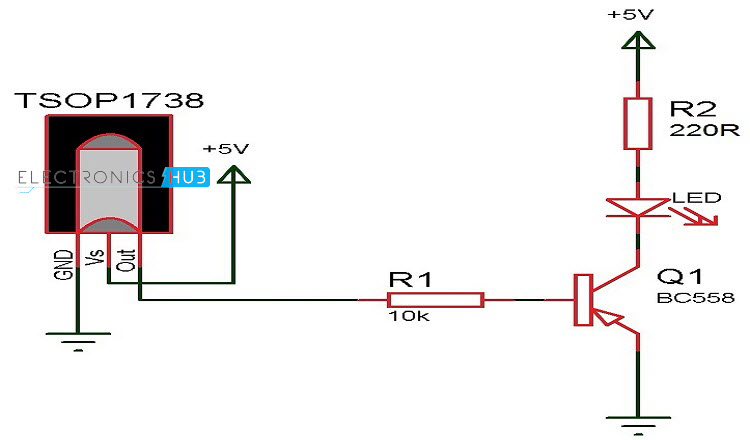
IR Receiver Circuit
Components Required
For IR Transmitter
- NE555 Timer IC
- 18 KΩ Resistor (1/4 W)
- 1 KΩ Resistor (1/4 W)
- 220 Ω Resistor (1/4 W)
- 1 nF Ceramic Capacitor (Capacitor Code 102)
- 10 nF Ceramic Capacitor (Capacitor Code 103)
- IR LED
- Push Button
- Breadboard
- Connecting Wires
- Power Supply
For IR Receiver
- TSOP 1738
- LED
- 220 Ω Resistor (1/4 W)
- BC558 PNP Transistor
- 10 KΩ Resistor (1/4 W)
- Breadboard
- Connecting Wires
- Power supply
Component Description
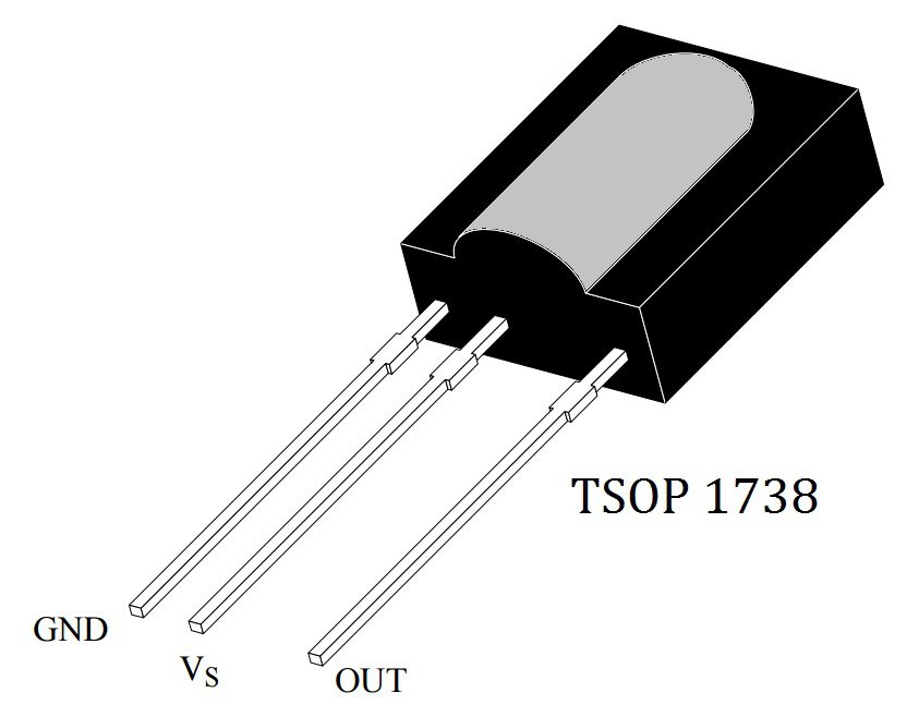
TSOP 1738 IR Receiver
TSOP 1738 is an IR Receiver for IR (Infrared) remote controls. It consists of Photo Detector, Gain Control, Band Pass Filter, Demodulator and a Pre – amplifier in a single package. TSOP17XX series of IR Receivers are very common for all types of transmission codes supporting different modulating techniques like RC6, RC5, NEC, Sony, etc.
TSOP 1738 in particular supports a carrier frequency of 38 KHz and the output of this IR Receiver can be directly connected to a microcontroller or a microprocessor. TSOP 1738 has three pins namely GND, VS and OUT. The following image shows the pin out of TSOP 1738.
 Some of the other characteristics of TSOP 1738 are high immunity to ambient light, active low output, low power consumption, continuous data transmission and compatibility with TTL as well as CMOS.
A typical application circuit of TSOP 1738 IR Receiver (or any IR Receiver for that matter) will consists of an IR Transmitter (IR LED), IR Receiver (TSOP 1738) and a microcontroller. The following image describes the block diagram of the IR Transmitter and Receiver.
In the image, the IR Transmitter emits Infrared light modulated at a particular frequency. The IR Receiver will receive this modulated signal and demodulates it and sends it to the Microcontroller.
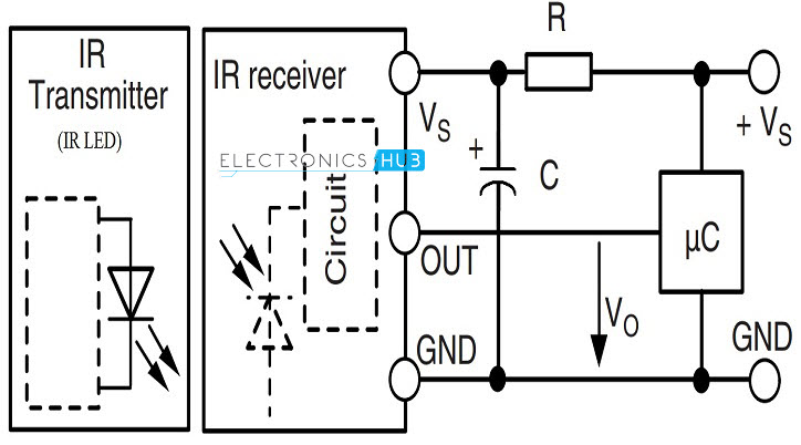 From the image it can be observed that the output of the IR Receiver is directly connected to the Microcontroller and there is no need for any extra interface. Also the Resistor R and Capacitor C are only used to suppress the power supply disturbances.
IR LED (Infrared Transmitter)
IR LED is a special type of LED that emits Infrared rays of the Electromagnetic Spectrum. The wavelength of Infrared Rays is greater than that of Visible light and hence they are invisible to human eye.
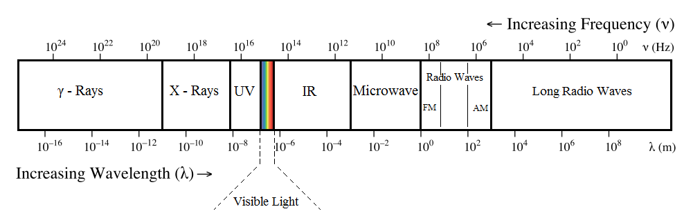
A typical IR LED emits infrared rays in a wavelength range of 740 – 760 nm. There are many sources of infrared light like sun, light bulbs, all hot items and even human body.
So, in order to prevent interference and false triggering, we will modulate the infrared light. The modulated signal can only be demodulated by the appropriate IR Receiver.
Circuit Design
The design of IR Transmitter and Receiver circuit is explained here. As mentioned earlier, we need to modulate the infrared light emitted by the IR LED. Since the IR Receiver used in this project is TSOP 1738, we need to modulate the IR Signals at nearly 38 KHz.
For this, we have used a simple 555 Timer IC in Astable Multivibrator mode. In this mode, the 555 IC will work as a free running oscillator and generates an approximate 38 KHz square wave. The output of the 555 IC is connected to an IR LED through a button.
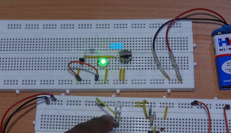
Coming to the IR Receiver circuit, the output of the TSOP 1738 is active low i.e. normally the output stays high and when it detects the infrared light, the output goes low. Hence, we used a PNP transistor to light up an LED whenever the IR Receiver detects infrared signal.
Working of the Project
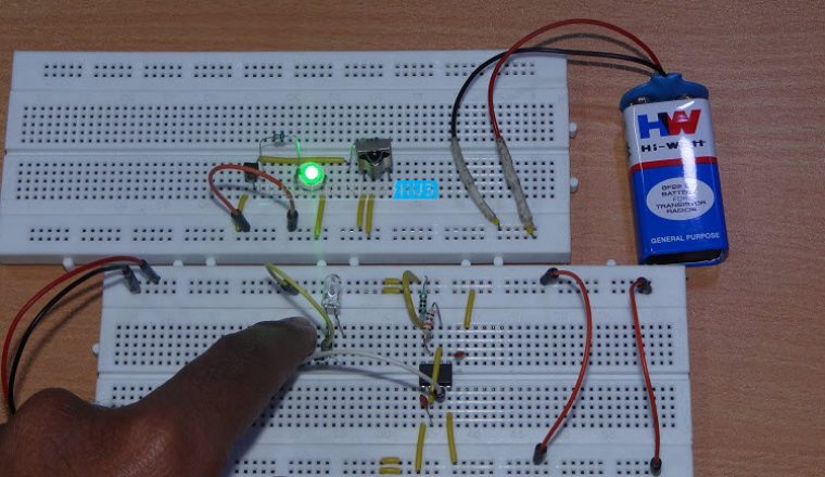
A simple project, which demonstrates the principle of Infrared (IR) communication using IR Transmitter and Receiver is explained here. The working of the project is as follows.
As mentioned earlier, the circuit is divided into IR transmitter and IR receiver circuits. The infrared rays emitted by the IR Transmitter i.e. IR LED must be detected by the IR Receiver i.e. TSOP 1738.
In the transmitter part, the 555 Timer is designed to operate in Astable Mode. Hence, it generates a continuous pulse and the frequency of the pulse is 38 KHz. When we push the tactile switch, the connection between IR LED and the output of the 555 Timer is closed and the IR LED emits the light at a frequency of 38 KHz.
When this modulated infrared light is placed in line of sight to TSOP 1738, it detects the signal and demodulates it. The output of TSOP 1738 is usually HIGH and when it detects IR Signals, the output becomes LOW. Since the output is connected to a PNP transistor (BC558), when the IR Receiver detects infrared signal, the transistor is switched ON and the LED connected to it is turned ON.
Advantages
- IR Transmitter and Receiver pair form a simple circuit which can be easily built.
- Can be used for simple remote controlling applications, small data transfer, etc.
- IR Transmitter and Receiver pair as a module can be used in security applications, proximity sensors, distance measurement applications, etc.
Disadvantages
- IR Transmitter and Receiver require line of sight communication i.e. they need to be facing each other.
- The range of IR communication is less and is reliable for short range and small amounts of data.

15 Responses
Hey,
I have IR receivers with two legs that i wanna use with my arduino. How would you do this on a breadboard?
Thanks
Hi, IR Receivers like TSOP1738 for example can decode signals from multiple sources. Try to decode all the IR Transmitters with a simple Arduino Code.
Nice article much appreciated.
What if I want to use a multiple number of transmitters and a single receiver?Can I encode the IR signals transmitter by IR LED so that I can decide them by using Arduino?
Hi, What you have is probably a Photo Diode. They can only detect Infrared light and cannot decode the signals.
Hi. What antenna did you use?
Hi, We did not use any antenna. You do not need an antenna for IR Communication.
Hi, is there a way to amplify the IR led transmitter? Because I want to place the IR receiver (e.g photodiode) 2-3 meters apart for the IR led.
Hi! I would like to ask if I’m going to replace TSOP 1738 by other TSOP that also has a 38Khz in it does it going to work too? Please answer ASAP. thanks
I have assembled this circuit, but i get very low voltage at the output of pin3. I get voltage 1.86V when i am giving supply of 9V
what is the maximum distance between them?
what is the maximum distance
How can i connect ir receiver to TDA7294 amplifier circuit
with wires.
i built this circuit and it works great. for infrared receiver to make it more useful i use 2 transistors and a relay to connect to the load. thanks