In this tutorial, we will see a brief Introduction to Transformers. We will learn what is an electric transformer, the construction of a transformer, its working principle, classifications of transformers, losses and efficiency and some applications.
Introduction to Transformers
A transformer is one of the most common devices found in electrical system that links the circuits which are operating at different voltages .These are commonly used in applications where there is a need of AC voltage conversion from one voltage level to another.
It is possible either to decrease or increase the voltage and currents by the use of transformer in AC circuits based on the requirements of the electrical equipment or device or load. Various applications use wide variety of transformers including power, instrumentation and pulse transformers.
In a broad, transformers are categorized into two types, namely, electronic transformers and power transformers. Electronic transformers operating voltages are very low and are rated at low power levels. These are used in consumer electronic equipments like televisions, personal computers, CD/DVD players, and other devices.
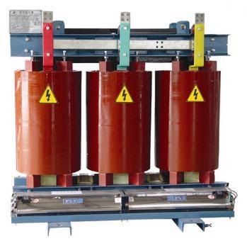
The term power transformer is referred to the transformers with high power and voltage ratings. These are extensively used in power generation, transmission, distribution and utility systems to increase or decrease the voltage levels. However, the operation involved in these two types of transformers is same. So let us go in detail about the transformers.
What is an Electric Transformer?
A transformer is a static device (means that has no moving parts) that consists of one, two or more windings which are magnetically coupled and electrically separated with or without a magnetic core. It transfers the electrical energy from one circuit to the other by electromagnetic induction principle.
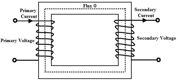
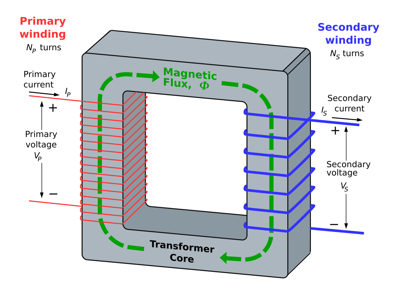
The winding connected to the AC main supply is called primary winding and the winding connected to the load or from which energy is drawn out is called as secondary winding. These two windings with proper insulation are wound on a laminated core which provides a magnetic path between windings.
When the primary winding is energized with alternating voltage source, an alternating magnetic flux or field will be produced in the transformer core. This magnetic flux amplitude depends on the applied voltage magnitude, frequency of the supply and the number of turns on the primary side.
This flux circulates through the core and hence links with the secondary winding. Based on the principle of electromagnetic induction, this magnetic linking induces a voltage in the secondary winding. This is called as mutual induction between two circuits. The secondary voltage depends on the number of turns on the secondary as well as magnetic flux and frequency.
Transformers are extensively used in electrical power systems to produce the variable values of voltage and currents at the same frequency. Therefore , by an appropriate primary and secondary turns proportion desired voltage ratio is obtained by the transformer.
Transformer Construction
The main parts of a transformer are core, windings, container or tank, bushings and conservator and radiators.
Core
For high power applications, transformer core is made with high permeability material which provides the low reluctance path for the magnetic flux. The cross section of the core would be square or rectangular.
Generally the iron core transformers provide better power transformation compared with air core transformers. Air core transformers are used for high frequency application (above 2 KHz) whereas , for low frequency applications (below 2 KHz) iron core transformers are employed.
In all types of transformers, core is made up of silicon steel or sheet steel laminations which are assembled to provide a continuous magnetic path for the flux. With this laminated core eddy current losses are minimized.
The thickness of these laminated sheets of steel are 0.35 to 5 mm and are insulated with a varnish, or oxide, or phosphate and then formed as a core.
For a better magnetic properties, Hot rolled grain oriented (HRGO) steel, or Cold Rolled Grain Oriented (CRGO) steel, or High B (HiB) laminations are used. In case of small transformers, core is constructed with hot rolled silicon steel laminations in the form of E and I, C and I or O are used.
Windings
Generally, the (two winding) transformer has two windings namely primary and secondary windings which are made up of high grade copper.
The insulated stranded conductors are used as windings for carrying high currents. This insulation avoids turns contacting with other turns.
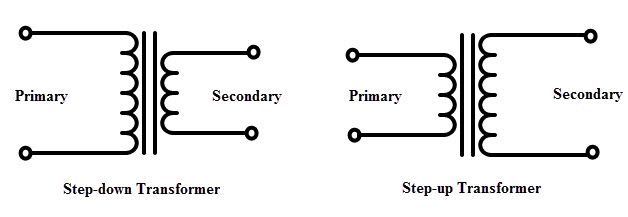
The voltage connected to the primary winding is called primary voltage whereas the induced voltage in the secondary is called as secondary voltage. If the secondary voltage is more than the primary, it is called as step-up transformer and if less, it is called as step-down transformer. Therefore, the windings are designated as HV and LV windings based on the voltage level.
Compared to the LV winding, HV winding needs more insulation to withstand high voltages, also needs more clearance to the core and the body.
The transformer coils can be concentric or sandwiched coils. Concentric coils are used in core type transformers whereas sandwiched coils are used in shell type transformers. In concentric arrangement, LV winding is placed near to the core and HV winding is placed around the LV winding for low insulation and clearance requirements. The most commonly used coils for the transformer include helical, sandwiched, disc and cross over coils.
Other necessary parts of the transformer are conservator tank which is used to provide the necessary oil storage such that the pressure of the oil under heavy loads settles down. When the oil in the transformer subject to the heat, naturally, oil expand and contract. Under this, oil is subjected to heavy pressure so without a conservator tank, there will be a chance of bursting the transformer.
The bushings provide the insulation to the output terminals to be taken from the windings of the transformer. These can be porcelain or condenser type bushing and based on the level of operating voltage these are selected.Because of simple, durable and rugged construction, transformers require a little maintenance. Because of no moving parts, the efficiency of the transformer is very high which may vary from 95% to 98%.
Classification of Transformers
Transformers are classified into several types depends the various factors including voltage ratings, construction, type of cooling, number of phases of the AC system, the place where it is employed, etc. Let us discuss some of these types of transformers.
Based on Function
Transformers are classified into two types based on the conversion of voltage level. These are step-up and step-down transformers.
Step-up Transformers
In step-up transformer, the secondary voltage is more than the primary voltage. This is due to the lesser number of coils in the primary compared to the secondary. This type of transformer is used to raise the voltage to a higher level. These are used in transmission systems and are rated at higher power levels.
Step-down Transformers
In step-down transformer, secondary voltage is less than the primary voltage due to the less number of turns in the secondary winding. Hence, this type of transformer is used to reduce the voltage to specified levels of the circuit. Most of the power supplies use the step-down transformer to keep the circuit operating range to a specified safer voltage limit. These types of transformers are used in distribution systems (power transformers) and in electronic circuits (electronic transformers).
It is to be noted that the transformer is a reversible device, so it can be used as both step-up and step-down transformer. For example, if the circuit needs a high voltage we will connect the HV terminals to the load whereas the load or circuit needs a low voltage, we will connect the LV terminals to the load.
The ratio of the voltage of a transformer is determined by the turns ratio. With the use of larger number of turns in the winding, higher will be the voltage produced in it. Hence, a step down transformer has lesser number of turns on secondary to produce a low voltage and has more turns on primary to withstand high voltage levels of the AC supply.
Turns Ratio = Primary Voltage/ Secondary Voltage = Primary Turns/ Secondary turns
The turns ratio is, VP /VS = NP /NS
Based on Core Construction
Based on the construction, transformers are classified into two types in the manner in which the windings are placed around the core. These types are core and shell type transformers.
Core Type transformer
In this type of transformer, windings surround the considerable part of the core. Generally, distribution transformers are of core type. Some of the large power transformers are of shell type.
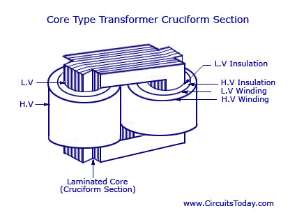
Form-wound, cylindrical coils are used in the core type transformers and these coils may be rectangular, or oval, or circular. For small size core type transformer, a simple rectangular core with a cylindrical coil in either circular or rectangular form is used.
And for a large sized core type transformer, cruciform core with round or circular cylindrical coils are used. In most of the core type transformers, cylindrical coils are used due to their mechanical strength. These cylindrical coils are wound in helical layers and are insulated from each other by insulating materials like cloth, paper, mica, etc.
It is easy to insulate the LV winding compared to the HV winding; hence it is placed nearer to the core.
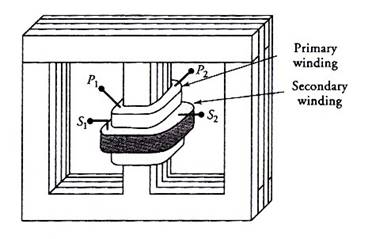
Shell Type Transformer
In a shell type transformer, iron core surrounds a considerable portion of the copper winding as a reverse case to the core type transformer. In this type also, coils are former wound, but are of multilayer disc type coils which are wounded in the form of pancakes. These multilayer disc coils in different layers of are separated each other by paper. The whole winding consists of stacked discs and in between the coils the insulation space is provided to form the horizontal insulating and cooling ducts.
Berry transformer is the most commonly used shell type transformer. In shell type, core has three limbs and the windings are wound around the central limb. Both LV and HV windings are divided into different coils which are arranged alternately. Between the LV windings, HV windings are sandwiched. Again to reduce the insulation requirement, LV windings are placed adjacent to the core. This type of construction is preferred for high rating transformers.
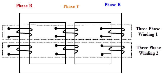
Based on Nature of Supply
Based on the nature of the supply, transformers can be single or three phase transformers. Single phase transformers are designed to work on a single phase system; therefore it has two windings to transform the voltage levels. These are used in remote ends of the power distribution system. These have less power rating compared with three phase transformers. Mostly core type construction is used for this type of transformer.
To work with three phase system, we need three single phase transformers. Thus, for an economic advantage, three phase transformer is considered for three phase operation. It consists of three windings or coils which are connected in a proper way to match the input voltage. This type of transformers, primary and secondary windings are connected in the form of star- delta or delta-star fashion depending on the load voltage requirements
Based on Use
- Power transformer
- Distribution transformer
- Instrument transformer
Other Types of Transformer
Based on the type of cooling these are classified into
- Self air cooled transformer
- Air blast cooled transformer
- Oil filled self cooled transformer
- Oil filled water cooled transformer
- Oil filled forced oil cooled transformer
Working Principle of Transformer
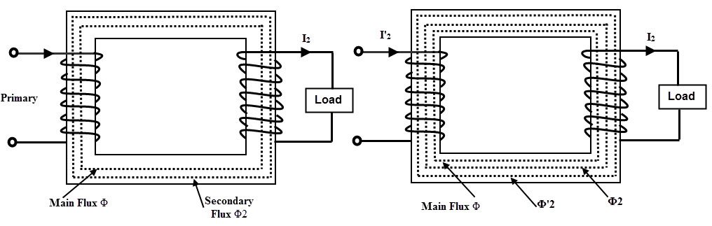
The operation of the transformer is based on the principle of mutual induction between two coils or winding which are linked by a common magnetic flux. When the primary winding is energized with AC source supply, a magnetic flux is established in the primary winding.
This flux is linked with both primary and secondary windings because the core provides a low reluctance path for the magnetic flux. Hence, most of the flux produced by the primary winding links with the secondary winding. This is called as main flux or useful flux. And also, the flux which does not link with the secondary winding is called as leakage flux. Most of the transformers are designed to have low leakage flux to reduce the losses.
According to the Faraday’s laws of electromagnetic induction, this flux linkage with both primary and secondary windings induces EMFs in them. This EMF induced in each winding is proportional to the number of turns in it. The voltage or EMF induced in the primary winding is called as back EMF which opposes the input supply voltage to the extent that no primary current would flow.
But small magnetizing current flows through the primary of the transformer. The EMF induced in the secondary winding is the open circuit voltage. If the secondary circuit is closed or the load is connected, secondary current starts flowing through it which causes to create demagnetizing magnetic flux. Due to this demagnetizing flux, the unbalance is created between the applied voltage and back EMF.
To restore the balance between these two, more current is drawn from the supply source so that equivalent magnetic field is created to balance with secondary field.
Since the same mutual flux cuts both windings, the EMF induced in the each turn of both windings are same. Hence the total induced EMF in each winding must be proportional to the number of turns in that winding. This turns out for the establishment of well-known relationship between induced EMF and the number of turns. And is given as
E1 /E2 = N1 / N2
Since the terminal voltages of the both windings are slightly different from their induced EMFs, we can write as
V1/V2 = N1/N2
This is called as the transformation ratio of the transformer. This transformation value is greater than unity in case of step-up transformer and less than unity in step-down transformer.
In terms of ampere turns balance,
I1N1 = I2N2
I1/I2 = N2/N1
Transformer Equivalent Circuit
An equivalent circuit of a machine or device is merely an interpretation of the equations that combines the fixed and variable resistors and reactances, which exactly simulates or describes the complete behavior of the machine.
Generally, the problems related to voltage and currents of a transformer can be solved by using phasor diagrams. However, to make the computations easy, it is very convenient to represent the transformer by an equivalent circuit.
With application of direct circuit theory to this equivalent circuit, we can easily find out the current and voltages in the transformer.
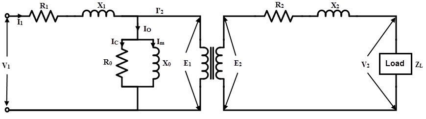
The above figure shows the equivalent circuit of the transformer in which it is imagined that the resistance and reactance of both primary and secondary windings are external (shown separately) to the winding. The no load current Io is the combination of magnetizing component Iu and active component Iw.
Hence, the effect of magnetizing current is represented as Xo and the effect of active component or core loss component is represented by the non inductive resistive Ro. Both Ro and Xo connected across the primary winding as shown in figure. This parallel combination is called as the equivalent circuit on NO load condition.
When the load is connected to the secondary, the current I2 starts flowing through the secondary circuit and causes the voltage drop across the X2 and R2. As mentioned above, due to the secondary current I2, primary draws more current. So the primary current I1 causes a considerable drop across the R1 and X1.
To make the calculations simple, equivalent circuit is further simplified by transferring the secondary resistances and reactances to the primary side such that the E2/E1 ratio is not affected in both phase and magnitude.
The primary equivalent of the secondary EMF is
E2’ = E2/K
Where K is the transformation ratio
Similarly the primary equivalent of secondary terminal voltage is
V2’ = V2/K
The primary equivalent of secondary current is
I2’ = I2/K
Let R2’ is the resistance to be transferred to the primary side that produces the drop in primary as same as it produced in the secondary. So I2’R2’ is the voltage drop in the primary by the R2’. This turns out that the ratio of I2’R2’ and I2R2 must be same as the N1/N2 (turns ratio).
Therefore,
(I2’R2’) / (I2R2) = (N1/N2) = (1/K)
R2’ = R2 × (I2 / I2’) × (1/K)
But (I2 / I2’) = (N1/N2) = (1/K)
Therefore, R2’ = R2 /K2
Similarly, X2’ = X2 /K2
In the same way, the load resistances and reactances can also be transferred to the primary side. With all these transferred values, the exact equivalent circuit of the transformer is shown in below.
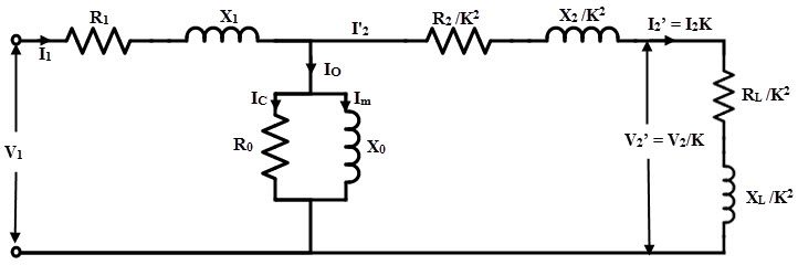
It is also possible to transfer the primary resistance and reactance (or simply impedance) to the secondary just as the secondary resistance and reactance (or impedance) transfer to the primary. Let R1’ and X1’ are the resistance and reactance transferred to the secondary side from primary, then
R1’ = K2R1
X1’= K2X1
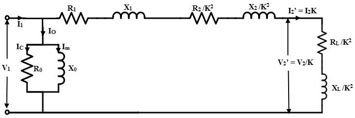
It is noted that the no load current is a small fraction of full load current and also E1 differs from V1 by a small amount and hence the current I2’ is practically equal to the I1.
So, the voltage drops due to the no load current Io across the R1 and X1 are neglected. Therefore, the exact equivalent circuit further simplified by shifting the no load parallel branch to the left that consisting of Ro and Xo to the extreme left position as shown in below figure.
This circuit is called as appropriate equivalent circuit of the transformer referred to the primary side. Hence the analysis becomes simple by adding series resistances and reactances.
Losses in Transformer
The transformer has no moving parts and hence the mechanical losses are absent in it. Hence, the losses in the transformer are considered as electrical energy losses. Two types of electrical losses are exist in a transformer which are core losses and copper losses.
Core or Iron Losses
These losses include both hysteresis and eddy current losses.
The magnetic flux set up in the transformer core is alternating type; thereby it undergoes a cycle of magnetization and demagnetization. During this, an appropriate power is required for continuous reversal of elementary magnets of the iron core. This is called as hysteresis effect and due to this considerable loss of energy takes place.
Hysteresis loss = Kh Bm1.67f v Watts
Where,
Kh = Hysteresis Constant
Bm = Maximum flux density
f= frequency
v = volume of the core
Since the transformer core is made up of ferromagnetic materials that are also good conductors. And hence, the magnetic flux linking with core induces emf in the core. Hence the core set up eddy currents in the core, thereby considerable eddy current losses occurs in the core.
Eddy Current losses = Ke Bm2f2t2 W/unit volume
Where,
Ke = Eddy current constant
t = thickness of the core
From the above two equations, it is to be observed that the supply voltage at a fixed frequency is constant and hence the flux in turn flux density in the core is almost constant. Therefore, both hysteresis and eddy current losses are constant during all loads. Hence the core losses are also called as constant losses.
By using the high grade core materials like silicon steel having very low hysteresis loop, hysteresis losses are minimized or reduced. On other hand, eddy current losses are minimized by using laminated core. These constant or core losses can be measured by conducting an open circuit on the transformer.
Copper Losses
These losses occur in the winding resistances of the transformer when it carries load current. The total copper loss in the transformer is obtained by adding both primary and secondary copper losses. These are found by conducting short circuit rest on the transformer.
Other losses in the transformer include dielectric losses and stray load losses. The stray losses are results from the eddy currents in the tank and winding conductors. Dielectric losses are occurs in the insulating materials like oil and solid insulations of the transformer.
Transformer Efficiency
It is the ratio of useful power output to the power input of the transformer operating at a particular load and power factor.
Efficiency = Output/ Input
= Output / (Output + Total Losses) or
= (Input – Losses)/Input
= 1- (Losses/ Input)
Generally the efficiency of the transformer is in the range of 95 to 98%. From the above efficiency equation, it may be noted that the efficiency is depends on the watts, but not in volt-ampere rating. Hence, at any volt-ampere rating, the efficiency of the transformer depends on the power factor. The efficiency is maximum at unity power factor and is determined by calculating the total losses from OC and SC tests.
Applications of Transformers
- Step-up or step-down the level of the voltage in power transmission systems like transmission and distribution systems.
- To isolate the low voltage circuits from high voltage circuits in case of substations, control circuitry circuits in industries, etc.
- Instrument transformers like current and potential transformer are used in protection and meter indication systems.
- These are also used for impedance matching.

3 Responses
Very informative. .
Thanks.
It’s really very helpful information,, thanQ so much.
Dear what is the transformer formula calculation?
I saw some 42, and some 7.5 or 7, I don’t undrestand what is the correct one.