Inductor consists of wire wound around a core of ferrite material that includes an air gap. Inductor stores the energy in the form of the magnetic field. Inductor has many electrical properties when subjected to a magnetic field.
One of the important property of this inductor is whenever the current flows through the wire it creates the magnetic field around it. If we coil the wire , the magnetic field is stronger. When the electric current flows through the coil the magnetic flux will increase exponentially and stabilize at particular point, then stores the electric energy in the form of magnetic energy. When electric supply stops then the magnetic energy will decreases exponentially and turns back into electrical energy. By this we can say that it will temporally store the energy. The faster the change in the magnetic field the induced emf or voltage will be greater. To know about current and magnetic flux relation let us know Lenz’s Law.
Lenz’s Law Overview
Before going to Lenz’s Law first we have to know about Faraday’s Law of induction. It states that the magnitude of emf induced in the coil is equal to the rate of change of flux that links with the coil. This is equated as below
ᶓ α dΦ/dt
Whereas the product of number of turns in the coil and flux related with the coil gives us the flux linkage.
Lenz’s Law states that an emf is generated by change in magnetic flux as stated in faraday’s law. The polarity of this induced emf is such that it produces a current such that magnetic field opposes the change which produces it.
ԑ = -N (∂ΦB / ∂t)
Where ∂ΦB = change in the magnetic flux
ԑ = induced emf
N = no. of turns
A = Area of the coil
u = permeability of the core.
L = Length of the coil
di/dt = Rate of change of current in the coil.
Working of inductor
When the electric current is flowing in the coil, the coil will build up the magnetic field around it. At the time of building the field , coil inhabits the flow of current and once if the field is build, current can flow normally through the wire. Due to this reason there will be exponential increase in the magnetic flow before reaching the steady state. When the electric current is turned off then the magnetic field around the coil will keep the current flow in the coil until the field collapses. This makes the electric current to decrease exponentially before it reaches its actual state.
When the wire is coiled as a series of continuous loops , it is called as solenoid. In this type , the magnetic field strength will increase or decrease with the increasing and decreasing currents respectively. It is similar to effect of bar magnet but with the variable field strength.
Inductor Symbols
The symbol of Air core
![]()
The symbol for Iron core
![]()
The symbol for Ferrite core
![]()
The symbol for Variable core
![]()
Inductance of Inductor
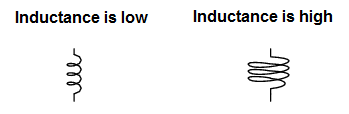
Inductance is the property of an Inductor .The current generated in the inductor due to magnetic field is proportional to the rate of change of magnetic field is called as inductance. Higher the inductance value, more the inductor will resists from the sudden changes in the current.
Inductance is given by L = µN2A / l
Where
L – Inductance of the coil.
µ – Permeability of the core.
N-Number of tuns in the coil
A-Area of the coil.
l -Length of the inductor.
Self-inductance
A change in the current causes change in the voltage in that circuit due to the magnetic flux generated by the current flow. Simply inductance within the coil gives us self-inductance. Chokes are best example for self-inductance effect.
Mutual-inductance
A change in the current in one circuit causes the change in voltage of next circuit .The linkage of magnetic field between both circuits leads to mutual inductance. Transformers are best example for mutual inductance effect.
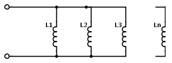
Inductors in series
When ‘n’ number of inductors are connected in series the total inductance value is the sum of all the individual inductances.
![]()
Ltotal = L1+L2+… +Ln
Inductors in parallel
When ‘n’ numbers of inductors are connected in parallel the total inductance value is the low and is equated as follows
Ltotal = 1/ ((1/L1) + (1/L2) +..+ (1/Ln))
If we observe these two equations these are very similar to the resistors connected in series and parallel.
Inductance Units
The SI unit of inductance is Henry. It is named after the American physicist Joseph Henry. This is denoted by ‘H’.
One Henry is nothing but the rate of change of current in a circuit is one ampere per second , then the resultant emf is one volt. This is equated as
H= (V.s)/A = Wb/A.
Where V = Volts, s = second, Wb = Weber, and A = Ampere.
Inductance Prefixes
1mH = 1 milli-Henry = 10-3 H
1μH = 1 micro-Henry = 10-6 H
1nH = 1 nano-Henry = 10-9 H
Factors influencing inductance
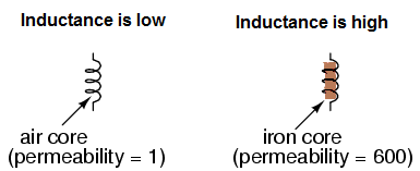
1.Material of the core
One of the important factor that affects the inductance value is permeability. If the magnetic permeability of the core is more the inductance is more and if this permeability of the core is less, the inductance is also less. Because a core with higher permeability will generate greater amount of magnetic flux for any given amount of field force.
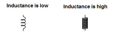
2.Number of turns of the inductor
If the number of turns of the inductor increases, inductance also increases. Because for any given amount of current , the amount of generated magnetic flux is always greater , if the inductor consists of more number of turns.
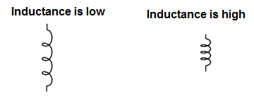
3.Length of the coil
If the coil length increases the inductance decreases. If the length is decreased, inductance is increased. For any amount of given current , for longer length of coil the generated magnetic flux results in more opposition to the generation of that flux.
4.Area of the coil
By taking the cross-sectional area of the coil, if the area increases the inductance increases and if the area decreases, value of the inductance will comparatively decreases. As the area increases more flux is induced and inductance is more.
The inductance value can also be affected by the external effects caused by the other wires and components which are near by the inductor, once it is assembled in the circuit. For accurate inductance value the approximated inductance value has to be calculated.
Let us consider a solenoid wound with a single layer of turns with some diameter of the wire and the turns are placed evenly then the typical formula for approximating the inductance value is given as follows.
L = (d2n2)/(l + 0.45d)
Where
d = diameter of the coil in meters.
n = no. of turns in the coil.
L = inductance in henry.
l = length of the wire in meters.
Current, Voltage and power calculation
The voltage in an inductor will depends on the rate of change of current through the inductor. Whenever the change is created that initial change is opposed by the induced emf. The emf induced in the coil will be same but the voltage will acts like a source with increasing current and voltage will acts like a load with decreasing current.
The work done by the source in order to remain the current flowing through the coil against the induce emf is power. It is given as
P = d/dt (½ (L x I2)).
The magnetic field density B (t) which is measured in tesla is equal to the magnetic field strength H (t), multiplied by the magnetic core permeability ‘μ’ .
This is given as
B (t) = μ x H (t).
The magnetic flux which is measured in webers, equal to magnetic flux density B (t), multiplied by the cross-sectional area of the core ‘Ac’.
This is given as
Φ(t) = Ac x B (t).
The energy stored in an inductor is equal to the amount of work done to establish the current flow through the inductor and to generate magnetic flux.
This given as
E = ½ (L x I2)
Where
L = Inductance,
I = current flow through the inductor and
E = Energy stored.
Example
Let us consider the following circuit with current flowing through the coil is 5 A.
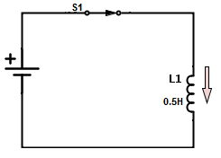
If the switch is opened for 15 milli-sec then the emf induced in the coil is given as
VL = L di/dt = 0.5 (5/0.015) = 166 volts
Quality Factor
Since the inductors are formed by the electrically conductive metal wire , they will have a series resistance. This series resistance will generate heat by converting the electric current flowing through the coil. Due to this heat the sensitivity of the inductor decreases. Thus the quality factor is nothing but the ratio of the inductance to the resistance. This is given as
Q = ω L/R
Where
Q = quality factor
ω = angular frequency (Hz)
L = inductance (H)
R = resistance (Ω)
Back EMF generated in an inductor: The EMF produced in the inductor will depends on the source currents that is either the current is AC or DC.
The self-induced emf VL = – L di/dt is applicable only for the AC current because there will be rate of change of current that is di/dt is not equal to zero. If the flow of the inductor current is constant , that is at DC current the di/dt is zero. At this stage the inductor acts like a piece of wire.
Time constant of an inductor: Let us consider the circuit as shown below with an inductor and an open switch.
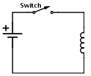
Since the switch is open there will be no flow of current in the circuit. Thus the rate of change of current di/dt is zero at this condition. We know that when di/dt is zero there is no self-induced emf in the circuit.
When we close the switch the current will flow through the circuit and slowly rise to its maximum value at the rate determined by the inductance of the inductor. The rate of current which flows through the inductor multiplied by the inductance gives us VL. Thus there will be self-induced emf (VL) in the circuit and this value depends on the inductance value of the inductor in the circuit VL= L di/dt .This VL will fights against the applied voltage until the current reaches its maximum value and reaches the steady state. At this stage only the coils D.C resistance will exists to oppose the current flow. Because in DC inductor the variation of current take place only during the transition state that is from zero to maximum and maximum to zero. Since DC is zero frequency component there is no reactance offered by the circuit in steady state condition.
Again when the switch is opened the current flowing through the circuit will fall , but the inductor again will fight against this change and try to keep the current flowing at its previous value by inducing the voltage in the other direction.
Inductor Applications
- Inductor with inductances in the nano-henry range , will only filter out very high frequencies i.e., above 100 MHz so these are mainly used in radio frequency circuits like old boom box in 1980s.
- Inductors in micro-henry range will filter out the frequencies about 50 KHz to few MHz. These are typically used in D.C. power supplies to smooth out the voltage.
- Inductors in milli-henry range are very effective and these are used in audio crossover circuits to separate low and high frequency sounds.
- Inductor ideally acts like a low pass filter since the impedance of an inductor increases as the frequency of a signal increases.
- Since inductor will sense the magnetic fields from a distance these are used in inductive sensors. These inductive sensors are used in traffic signalling to detect the amount of traffic.
- By combining two inductors which have a shared magnetic field will acts like the transformer. These inductive based transformers are applicable only at lower frequencies.
- In fixed speed applications inductive motors are used.

2 Responses
very good!!!
thanks u very much for this productive totur