Relays can be used for switching as well as protection application. A relay is used to switch a circuit such that current through it can be diverted from present circuit to another. This switching operation can be performed either manually or automatically. Manual operation for switching a relay is performed through push buttons and other conventional switches. In most of the cases control circuit output drives the relay for automatic operation.

Protective relays are used to ensure the smooth operation of any power system such that they isolate the particular circuit or generate the alarm whenever parameters like voltage or current exceeds their limits. Therefore the principal function of the relay is to make or break the circuit in switching and protection applications. A variety class of relays is found in several applications. This article gives you a brief idea on the electromechanical relay and also different types of relays.
Electromechanical Relays
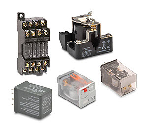
A relay is an electromechanical device having electrical, magnetic and mechanical components. The relays control the electric circuit by opening or closing the contacts of that circuit. An electromechanical relay consists of three terminals namely common (COM), normally closed (NC) and normally opened (NO) contacts. These can either get opened or closed when the relay is in operation. These relays can work on both AC and DC supply sources.
The construction is somewhat different for AC and DC relays, but both work on the principle of electromagnetic induction. In case of AC relays, for every current zero position, the relay coil gets demagnetized and hence there would be a chance of continues breaking of the circuit. So, AC relays are constructed with special mechanism such that continues magnetism is provided in order to avoid above problem. Such mechanisms include electronic circuit arrangement or shaded coil mechanism.
Most of the electromechanical relays are either attracted type or induction type.
Attracted type electromagnetic relay works on AC as well as DC in which armature is attracted towards the electromagnet or armature through a plunger is drawn into a solenoid. All these relays are working on the principle of electromagnetic attraction. The electromagnetic force experienced on the armature or plunger is proportional to the square of the current or the square of the magnetic flux in the air gap. These are again classified into several types such as hinged armature type, plunger type, balanced beam type, moving coil type and reed type relays.
Induction type relays are working on the principle of electromagnetic induction. These types of relays are used only with AC source. In these relays, the actuating force is developed by the moving contact which can be a disc or cup through the interaction of two alternating magnetic fluxes on a magnetic element. Induction type relays are classified into shaded pole, induction cup type and watt-hour meter relays.

Relay Operation
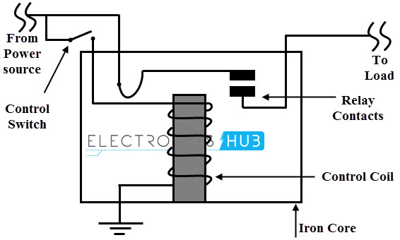
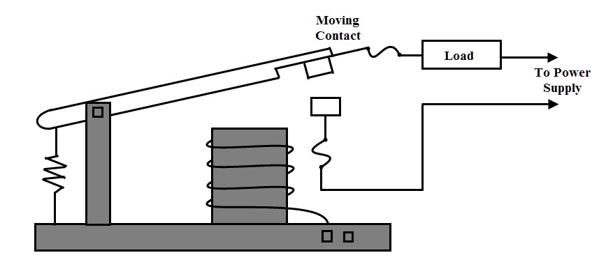
The figures below illustrate the relay operation. For ease of understanding we have given attracted type electromagnetic type relay. In any type of electromechanical relay of the relay, the major components are coil, armature and contacts. A piece of wire is wound around a magnetic core so it forms an electromagnet. When the supply is given to this coil, it becomes energized and produces an electromagnetic field. An armature is a movable part and its main function is to open or close the contacts. It is attached with a spring so that under normal working condition this armature comes back to its original position. And the contacts are the conducting parts which connects the load and source circuits.
Under Energized Condition
If the coil is supplied by the source, the coil of the relay gets energized and produces a magnetic flux proportional to the current flowing through it. This magnetic field causes to attract the armature towards the electromagnet and hence both moving and fixed contacts are come closer to each other as shown in figure. In case of NO, NC and COM terminals (not shown in figure), both NO and COM terminals are get contact when the relay get energized while NC contact remains floating.

Under De-energized Condition
When the power is not supplied to the relay coil, there is no magnetic flux production and hence the armature is in stationary position. Therefore, both the contacts are remains untouched and there exists a small air gap between these contacts. In other words, NC and COM contacts are get in touch with each other when the coil is de-energized
Relay Contact Types
Relays come in a variety styles, configurations, sizes and technologies. Depends on the application, suitability of the relay is considered. Basically, a relay has three contacts which are necessary to connect the two circuits but the way these contacts are configured or switching action of the contacts, relays are classified into different types. Before we know about this classification of contacts we have to know the poles and throws of a relay switch.
Poles and Throws
Every relay or switch must have at least two contacts or terminals. These are signal in (or input) and signal out (or output) terminals. In switching or relay terminology, input terminals are corresponding to by the poles and the output terminals are represented by throws of a relay or switch. The number of poles of a relay indicates the how many individual circuits it can control while the number of throws defines the number of different outputs to be connected to input by each pole.
Depends on the poles and throws, relays are classified into
- Single pole single throw
- Single pole double throw
- Double pole single throw
- Double pole double throw
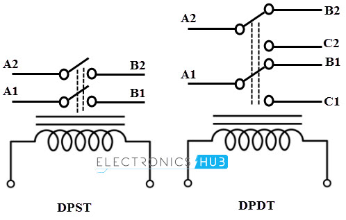
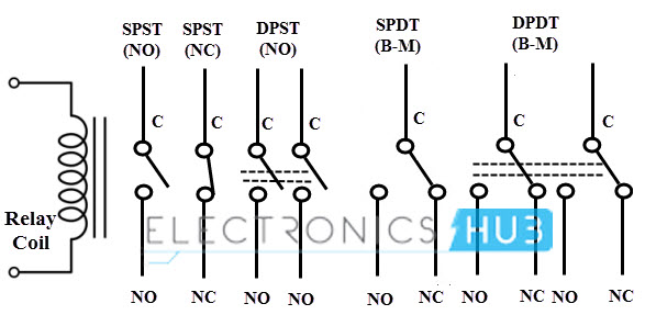
The below figure shows various types of relays based on their switching contacts. A single pole single throw relay can control one circuit and can be connected to one output. It is used for the applications which require only ON or OFF state. A single pole double throw relay connects one input circuit to one of the two outputs. This relay is also called as changeover relay. Though the SPDT has two output positions, it may consist of more than two throws depends on the configuration and requirement of the application.
A double pole single throw relay has two poles and single throw and it can be used to connect two terminals of a single circuit at a time. For example, this relay is used for connecting both phase and neutral terminals to the load at a time. A DPDT (double pole double throw) relay has two poles and two throws for each pole. In motor direction control, these are used for phase or polarity reversal. The switching action between contacts for all these relays is performed when the coil get energized as shown in figure below.
Normally Open and Normally Closed Contacts
A Normally Open relay indicates the switch open condition under coil demagnetized condition. Whenever the actuation is performed by the energized coil, the circuit gets closed as shown in figure a in which a simple SPST relay is used for performing the switching operation. Alternately a Normally Closed (NC) relay is connected to the circuit by default, even when the coil is demagnetized or unpowered condition.
Whenever the coil is energized these contacts become opened and thereby the active circuit is opened as shown in figure b. A relay can be configured with both these contacts as SPDT configuration by consisting NC and NO contacts in the relay itself as shown in figure c. Based on the application requirement, we can connect these NC and NO terminals so that it can be switched from make to break or break to make or switched between two circuits.
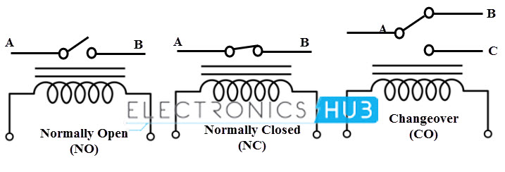
By considering the above relay contact concepts, we can obtain the relays with NO and NC contacts for various switching operations as shown in below figure.
Types of Relay
Relays can be classified into different types depending on their functionality, structure, application etc.
Driving a Relay
As we have discussed, a relay allows for switching a high power circuit with a low power circuit. So to make a relay operate, we have to energize the coil by passing a current through it. Therefore a driving circuit is necessary which nothing but a control circuitry of the relay. A relay driving circuit operates or drives the relay in order to perform switching function appropriately in a given circuit. Majorly there are two types of driving circuits for driving a relay namely AC relay driver circuit and DC relay driver circuit.
1. DC Relay Driver Circuit
There are numerous ways to operate a DC relay using different types of control devices ranging from simple transistor devices to high end integrated type devices.
a. NPN or PNP Driver
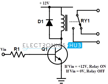
A simple relay driver is formed by using NPN or PNP transistor to control the current through the coil of the relay. A low power control circuit is needed to supply the base current in order to turn ON or OFF of the transistors. Below figure shows NPN transistor driven relay in which the relay coil is connected between the DC supply terminal and the collector terminal of NPN transistor. The resistor R1 limits the current flow to the base of the transistor and the diode D1 protects the transistor from damage due to the back emf generated in the relay coil when the transistor is turned OFF.
Whenever the base terminal is supplied with an appropriate current, NPN transistor is driven into saturation mode and hence it completes the path from supply to ground. The current flow through the relay coil produces the magnetic flux which is responsible to operate the relay contacts. This magnetic field attracts the relay contacts and thus relay is operated. When no base current is supplied, transistor is in cutoff mode and hence the relay coil is in de-energized condition.
Similar to the NPN driver, we can operate the relay by using PNP driver as shown in figure. In this the relay coil is connected between the emitter and ground terminals. In this driver circuit, the reverse operation will be performed as that of NPN relay driver.

b. 555 Timer IC Driver
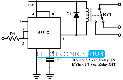
The above discussed driver circuits are very low in cost and are generally more flexible for driving the relays. However, in some cases the base current required by these circuits is bit low especially, when the control circuit is based on CMOS logic. In that case a relay can be operated by using 555 timer IC. This IC is well suited for driving the relay, in which 2 and 6 are shorted and connected to the input. The terminal 3 is the output pin connected to the relay coil as shown in figure.
When the inputs taken at the 2 and 6 terminals to a voltage more than the 2/3 of the supply voltage, the output at pin 3 goes low, while this voltage is less than the 1/3 of the supply voltage, then the output at pin 3 goes high. Between these switching of the timer, a relay (small relays) can be operated satisfactorily to control the power circuit. Diode across the relay coil is used to protect the timer from back emf produced by the coil.
c. Driver ICs
Alternative to the above discussed transistor and timer based driver circuits, relay driver ICs can drive multiple devices. These drives are ICs are of different types such as bipolar transistor driven ICs, Darlington pair driven ICs, MOSFET bridge type ICs, etc with various channel configuration like 8 channel, 16 channel, and so on. These ICs are allows to connect more than one relay coils in order to perform the switching application. Some of the popular relay driver ICs used in controlling the electronic equipments includes UL2803, ULN2003, TLC5940, etc.
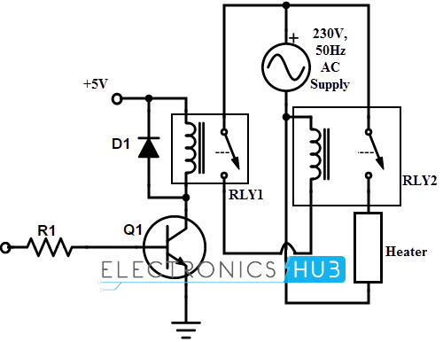
2. AC Relay Driver Circuit
The figure below shows the relay operation in an AC circuit. In this circuit relay is used to control the heater by using the relay. For controlling the main relay (relay 2), an auxiliary relay (relay 1) is used which is controlled by the DC control circuit. When auxiliary relay coil is energized by a transistor driver circuit, the path of the main relay is completed through relay 1 contacts. Thus the relay 2 coil is energized and hence it is operated to turn the heater. Similarly for turning OFF the heater relay 1 coil must be de-energized.
Relay Testing
Most of the electromechanical relays need regular checkups of their functionality for reliable performance. As the moving parts of the relay change in response to abnormal conditions there should be regular testing. Protective relays are used in medium and high voltage power system. With a long usage, the connection of the relay gets deteriorated with carbon particles. Therefore, in order to ensure the reliable performance of the relay, it must be tested before putting into service and also after time intervals it must be checked. These types of tests include
Acceptance Test
This is performed by the manufacture at several stages during manufacture in order to check the acceptability of the unit for sale.
Commissioning Tests
These tests determine the function of the relay for a particular protection scheme. These tests are carried to for checking accuracy of assembling the components in the relay, ratings, calibration and conformity with entire system.
Periodic Maintenance Tests
These tests are carried to identify the degradation of the service and equipment failures in the relay.
These are the tests that are carried on the relays which are employed for high and medium power switching or protection system applications. However, for low power application especially relays are that are used in electronic control systems, a multimeter is high enough to carry the relay testing. The procedure for testing the relay is as follows.
- Keep the multimeter selector in the continuity mode.
- Place the multimeter probes such that one probe at pole and other at NC contact and check for the continuity.
- Place the multimeter probes such that one probe at pole and other at NO contact and check for the discontinuity between the pole and NO contact.
- Now apply the rated voltage to the relay coil so as to energize the relay and then observe clicking sound engaged with the relay.
- Again check for the continuity between the pole and NO contact.
- Also check for discontinuity between the pole and NC contact.
- Finally remove the power supply. Place the selector of multimeter in resistance mode and measure the resistance of the relay coil. Check the measured resistance value with value stated by the manufacturer.
If above all conditions are met, then we can say that the relay working properly otherwise it is defective.
Relay Applications
Relays are used to protect the electrical system and to minimize the damage to the equipment connected in the system due to over currents/voltages. The relay is used for the purpose of protection of the equipment connected with it. These are used to control the high voltage circuit with low voltage signal in applications audio amplifiers and some types of modems. These are used to control a high current circuit by a low current signal in the applications like starter solenoid in automobile. These can detect and isolate the faults that occurred in power transmission and distribution system. Typical application areas of the relays include
- Lighting control systems
- Telecommunication
- Industrial process controllers
- Traffic control
- Motor drives control
- Protection systems of electrical power system
- Computer interfaces
- Automotive
- Home appliances

3 Responses
Great article sir, keep updating great stuff.
Thanks
Great Work.
Can I use NPN and PNP to drive a single relay.
If I connect the NPN to the Negative supply of the relay and the PNP to the Positive. So when the base of NPN has Volt the relay will get the normal Negative Volt and when the base of PNP has no Volt the Positive Volt will reach the relay positive pin, therefore, the relay is one in this condition but, in the base of PNP has Volt the relay has no Positive Volt and it will not activate.
Is that feasible?
Thanks!
Your content helped me a lot to take my doubts, thank you very much.