Actuators convert a given kind of energy into mechanical energy. There are different classes of actuators depending on the physical principle on which the energy conversion takes place.
Some of these classes of actuators which are widely used in industrial applications include hydraulic actuators, electrostatic actuators, electromagnetic actuators, thermal expansion actuators and pneumatic actuators.
In mechatronic system design the most important aspect is the selection of actuators because the characteristics of actuators are directly reflected to kinematic performance of the employed system. This article mainly concentrates on electromagnetic actuators, so let us go in detail about this topic.
What is Electromagnetic actuator?
An actuator which works based on the electromagnetic principle for energy conversion is called as electromagnetic actuators. Electromagnetic actuators convert electrical and mechanical energy into one another.
The energy conversion takes place in the so-called air gap which separates the stationary member (stator or fixed contact) and moving member (rotor or moving contact) of the actuator.
These actuators produce force and torque by means of magnetic field. Magnetic fields have higher energy density compared with electrical fields that’s the reason for using magnetic fields in these sensors.
The fundamental principles that govern electromagnetic actuators are faraday’s laws of electromagnetic induction, Lorenz force of electromagnetic forces and Biot-Savart law. Since the control variable of this kind of actuator is the electric current fed by the power converter drives, so these can be easily controllable.
These are used in many applications from precise control using small actuators to the quite large powerful units using electrical drives.
The electromagnetic sensors consist of two major circuits; namely electrical circuit and magnetic circuit. The electric circuit establishes voltage and current according to the circuit analysis laws whereas magnetic circuit establishes the magnetic flux and magnetic field strength.
In the presence of a magnetic field, magnetic flux Φ exists. The magnetic flux density B ̅ and magnetic field strength H ̅ are related by the permeability of the material. In a vacuum, the magnetic flux density is proportional to the magnetic field strength and is given as
B‾ = µo H ̅
Where µo is the permeability constant and its value is 4π × 10-7. For ferromagnetic materials this relationship is given as
B ̅ = µr H ̅ . µo H ̅
Where µr H ̅ is the relative permeability of the material. By using B-H curves, the permeability (µr) of the material dependence on H ̅ is analyzed.
The Lorenz law states that when a current carrying conductor is placed in a magnetic field, it experiences a force. If a current i is flowing in a conductor of length L, in the presence of magnetic flux density B ̅, then the experienced
Lorenz force is given as
F ̅ = i L ̅ × B ̅
Most of the cases B ̅ and L ̅ are orthogonal, and by considering F ̅ orthogonal to B ̅ and L ̅ the above equation can be written as
F = B L i
The motion of a conductor in a magnetic field produces an electromagnetic force (emf) across the conductor. This is called as electromagnetic induction law or Faraday law. According to this law the emf induced in a closed circuit is equal to the rate of change of magnetic flux through the circuit.
Therefore, e = – dΦ/dt
And the Biot-Savart law describes the magnetic flux density generated by the electric current and for a long straight conductor at a perpendicular distance r, it is given as
B = (µo µr i) / (2πr)
These are the three important laws which act as fundamental principles for electromagnetic actuators.
Different Actuators based on Electromagnetism
In many fields such as automotive, industrial automation, protection system applications use the different types of actuators based on several factors like size, type of actuation needed, reliability, cost-effectiveness, etc. Some of the electromagnetic actuators are discussed below.
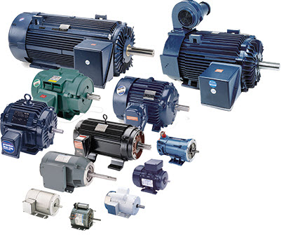
1. Electrical Motors
Electric motor is more generalized and commonly used electromagnetic actuator for widespread applications. The electric motor converts the electrical energy into mechanical energy. It consists of two parts stationary stator and rotating rotor.
When a stationary stator is excited with a magnetic field then current carrying rotor starts rotating based on the Lorenz force principle. These are classified either based on electromagnetic characteristics or functionality. This type of actuator classification is given below.
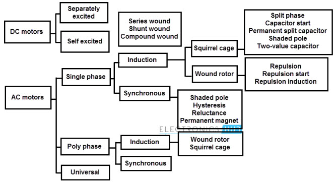
- Depending on the nature of supply, electrical motors are classified as DC and AC motors. DC motors are excited with Direct Current source and classified into two major types as separately excited motors and self excited motors. Self excited motors are again classified into shunt wound, series wound and compound wound motors. These motors easily controlled with moderate drives. And also these motors are available at reduced prices compared to the AC motors.
- AC motors are supplied with Alternating Current supply and are classified mainly into single and three phase motors.
- Single phase motors can be induction or synchronous motors. Single phase induction motor consists of single stator winding with squirrel-cage rotor and these are not self-starting motors. The torque is generated based in the electromagnetic induction between the stator and rotor. The rotor speed is slightly lower than the rotating field of the stator. Single phase synchronous motors consists either permanent magnet rotor or rotor winding with slip ring commutation. In these motors rotor speed is synchronized with the frequency of the supply source.
- Poly-phase or three phase motors can also be induction or synchronous motors. These are similar to the single phase induction motors but have multiple windings on its stator. These are self-starting motors. Three phase synchronous motors consist of multiple windings on its stator and the operation is similar to the single phase synchronous motors.
- Depending on the way of magnetic field is created; electrical motors are classified into two types namely permanent magnet motors and electromagnetic motors.
- A special class of motors includes stepper motors and brushless DC motors. Stepper motors are again classified into permanent magnet, variable reluctance and hybrid type of motors. These are used many electronic portable applications.
2. Solenoid Actuators
Solenoids are the simplest common electromagnetic actuator which converts the energy into linear or rotational motion. These are used in many applications including conveyor diverters, relay applications, coin dispensers, electric lock mechanisms, etc.
A solenoid consists of a soft iron core enclosed within a current carrying coil and a ferromagnetic plunger or armature in the center of the coil. When the current coil is energized, a magnetic field is induced in the coil.
This magnetic field pulls the armature or plunger to the center of the coil by closing the air gap between stationary frame or contact and plunger. Solenoid actuators can be linear or rotary type.
Linear Solenoid
Due to the linear directional movement or action of the plunger these solenoids are called as linear solenoids. These are of two types namely push and pull type linear solenoids.
In pull type solenoid, when the coil is energized it pulls the connected load (or plunger) towards itself whereas in push type it push the connected load away from it. The construction of both these types is same except the design of the plunger and the location of the return spring.
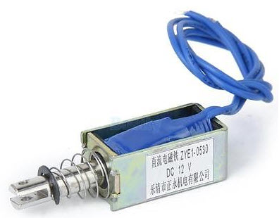
Linear Solenoid
The above figure shows the pull type solenoid that pulls the plunger when the coil gets energized. When the coil is de-energized, a return motion is provided by the load itself or by a return spring which is provided as an integral part of the solenoid assembly.
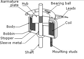
Rotary Solenoids
Rotary solenoid converts the linear motion to rotary motion by utilizing ball bearings that travel down inclined raceways. These solenoids produce rotary or angular motion in either clockwise or anti-clockwise or both from a neutral position.
When the angular movements required by the application is very small then these solenoids replaces the stepper motors and small DC motors.
When the coil of the rotary solenoid is energized, the armature or plunger assembly is pulled towards the stator. Further it is rotated through an arc determined by the coining of the raceways.
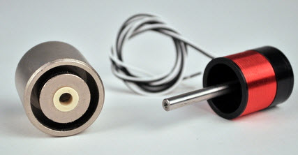
3. Moving Coil Actuators
These actuators are also called as voice coil actuators. It is also a kind of liner actuator which moves along a line. In this type of sensor, the coil is enclosed in a magnetic housing and excitation current is passed through this coil.
This current produces the magnetic flux from the coil windings. Based on the Lorenz force principle, a force is developed which is proportional to the product of magnetic field density and the current. The amount force generated is expressed as
F α N I B
Where
N is the number of turns in the winding
I is the current flowing through the winding and
B is the Magnetic flux density.
These types of actuators come in two shapes namely cylindrical and rectangular. With gears in its design makes simplicity of construction. These are used in many industrial, medical and auto mobile applications and some of the specific applications include beam steering mirrors, pilot valve control, gimbals assemblies, etc.
4. Relays
Relays are binary actuators which has two stable states as either latched and energized or unlatched and de-energized. A relay is a device that provides the switching action between two electrical circuits in response to the control signal.
These can be several types based on different criteria such as based on contact these are classified into single pole single throw, single pole double throw, double pole single throw and double pole double throw. Other popular relays include electromagnetic relays, solid state relays, latching relays, polarized relay, reed relay, etc.
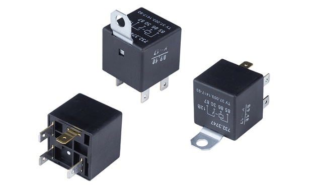
The above figure shows the attracted armature type electromagnetic relay. It consists of fixed and moving contacts. The load circuit is connected through the fixed contact whereas the power circuit is connected to the moving contact.
The control circuit supplies the power to the energizing coil. When the control circuit energizes the relay coil (or energizing coil), an armature being attracted towards the fixed contacts and hence the both source and load circuits get connected. When the power is not supplied to the coil, then the relay is de-energized.
Relays are mainly used as protection device for equipment connected with it. Also the basic function of relay is required by so many applications like telecommunication, home appliances, automotive, industrial control, electronic equipment control, etc.
MEMS Based Magnetic Actuator
A MEMS based magnetic actuator is a device that uses the MEMS (Microelectromaechanical systems) technology to convert the electrical energy to mechanical energy by employing a principle of Lorenz force equation.
MEMS based magnetic actuator produces a new class of micro devices which are fabricated using micro machined methods with a great potential and applications.
These devices are based on the magnetic or electromagnetic interactions between magnetic materials and the electromagnetic coils or magnetic fields sources such as permanent magnets. But the major challenge for this type of devices is the integration of magnet into the MEMS device.
This is due to the fact that it is very difficult to fabricate the 3D coils by the MEMS. Although attempts have been made to fabricate the magnetic actuation on micro scale with wire-bonded coils, very often MEMS magnetic actuators are compete with electrostatic devices.
These MEMS magnetic actuator platform has been developed for a broad range of potential applications which includes switches, relays, valves, resonators, optical switches, etc.
1. MEMS Switches
MEMS switches are different from solid state switches such as diodes and FETs although the purpose of interrupting the current flow is same.
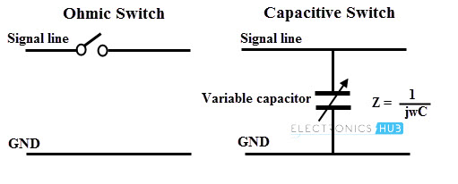
MEMS switches consist of mechanical moving parts to vary the distance between the two conductive elements of a signal line in order to make or break an ohmic contact in case of ohmic switches whereas in case of capacitive switches, it increase or decrease the enclosed capacitance. The figure below shows the switching principle of ohmic and capacitive devices.
These are comprised of an electrical element and actuation section which can be categorized depending on the actuation scheme such as magneto static, electrostatic, thermal or piezo-electric , the electrical configuration such as capacitive or ohmic contact switches, shunt or series circuit architectures , the geometrical configuration such as horizontal or vertical actuation, membranes, beams, cantilevers, etc.
These switches offer low power consumption and higher OFF-state isolation for high frequency switching compared with solid state switching devices. But they suffers with a problems of low speed and reliability.
2. MEMS Relays
The primary action of the relay is to switch ON or OFF such that they can make or break the circuit. MEMS relays are miniaturized mechanical relays which are fabricated based on MEMS technology.
The desirable characteristics of MEMS relays are good ON-state and OFF-state characteristics, gap between the contacts should be minimum, low contact resistance, large stand off voltage when relay is in OFF-state and the switching speed should be high.
However, the design of this devices are more complicate due to the three dimensional nature of magnetic coil that is not suited to MEMS fabrication. Advanced steps have taken to produce the MEMS relays such as lithographic methods which causes to several groups have succeeding in developing electromagnetic MEMS relays.
Due to high manufacturing complexity, the outlook of commercial relays success is uncertain. But for micro relay technologies electrostatic or electro thermal actuation principles are used.
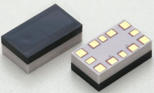
MEMS Relays
In the electrostatic drive mechanism based MEMS relays, two insulated conductive plates are separated by a small air gap which can be brought into contact by placing sufficient voltage across them. The relay action is performed by arranging the suitable conductors and contacts on the moving parts.
The electrostatic force varies as the square of the electric field generated in the actuator and the operating voltage increases linearly with the separation of the distance.
This is the main difficulty in designing the electrostatic actuated relay because it is difficult to achieve the reasonable contact gaps while keeping the actuation voltage in realistic range.

.JPG)
One Response
What is self latching in electromagnetic actuation method of MEMS switch?