In this tutorial, we will learn how to test a diode. Diodes are one of the basic and important components in electronic circuits that are used for protection, rectification, switching, and many other applications. They are one of the first components to be damaged in case of a fault and hence, it is necessary to know how to check whether a diode is properly working or not.
Diodes
If you are starting to develop your own electronics project or if you want to troubleshoot any electronic circuit or project, then you must have a sound knowledge on basic electronic components and their working. You don’t have to understand its construction and internal working but at least some basic knowledge on how a component works, how to test a component and see whether the component is working properly or not.
Learn more about the basics of Semiconductor Diodes.
Having knowledge on how to test a component and assessing whether it is good or not is a very good electronic circuits troubleshooting skill.
To avoid getting undesired results, it is advisable to test all the basic components like a resistors, diode, LED etc., for their normal working or operation before assembling the components in a circuit (PCB). In the worst case scenario, if we do not perform any tests before assembly and if the output is not as expected, then it is very difficult to identify the source of the problem and we have test all the components (which is very difficult after assembling).
Let us focus on Testing Diodes in this tutorial. As mentioned earlier, diodes are one of the important components in electronic circuits, especially in Power Supplies (and there are many other applications of diodes).
How to Test a Diode?
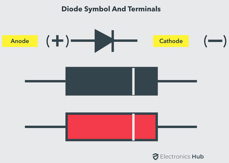
The diode is a two terminal semiconductor device that allows current to flow only in one direction. These are found in different applications like rectifiers, clampers, clippers and so on.
When the anode terminal of the diode is made positive with respect to cathode, the diode is said to be forward-biased. The forward-biased diode voltage drop is typically 0.7V for Silicon diodes. This is the minimum potential difference between Anode and Cathode of the Diode to become forward biased.
Before testing a diode, we have to first identify the terminals of the diode i.e., its Anode and Cathode. Most of the PN Junction diodes have a white band on its body and the terminal near this white band is the cathode. And the remaining one is anode. Both through-hole and surface mount Diodes have this marking.
Some diodes may have a different color band (for example, some Zener Diodes have a Black marking on its Red / Orange body), but the terminal near this colored mark is almost always the cathode.
The testing of a diode can be carried in different ways, however here we have given some basic testing procedures of the diode.
NOTE: The below mentioned testing procedures are only for normal PN diode.
NOTE: If the diode you want to test is already in a circuit (on the PCB), then you can perform the following mentioned tests by removing / de-soldering only one lead of the diode.
How to Test a Diode using a Digital Multimeter?
The diode testing using a Digital Multimeter (DMM) can be carried in two ways because there are two modes available in DMM to check the diode. These modes are:
- Diode Mode
- Ohmmeter Mode (or Resistance Mode)
The Diode Test Mode is the best way to test a diode as it relies on the characteristics of the Diode. In this method, the diode is put in forward bias and the voltage drop across the diode is measured, using a Multimeter. A normally working diode will allow current to flow in forward bias and must have voltage drop.
In the Resistance Mode Test of the diode, both the forward and reverse bias resistances of the diode are measured. For a good diode, the forward bias resistance should be few hundreds of Ohms to few Kilo Ohms and the reverse bias resistance should be very high (usually indicated as OL – open loop in a multimeter).
Diode Mode Testing Procedure
- Identify the anode and cathode terminals of the diode.
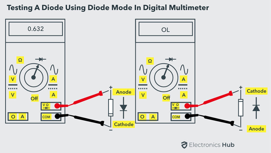
- Keep the Digital Multimeter (DMM) in diode checking mode by rotating the central knob to the position where the diode symbol is indicated. In this mode, the multimeter is capable to supply a current of approximately 2mA between the test leads.
- Connect the red probe of the multimeter to the anode and black probe to the cathode. This means the diode is forward-biased.
- Observe the reading on multimeter’s display. If the displayed voltage value is in between 0.6 to 0.7 (for a Silicon Diode), then the diode is healthy and perfect. For Germanium Diodes, this value is in between 0.25 to 0.3.
- Now, reverse the terminals of the meter i.e., connect the red probe to cathode and black to anode. This is the reverse biased condition of the diode where no current flows through it. Hence, the meter should read OL or 1 (which is equivalent to open circuit) if the diode is healthy.
If the meter shows irrelevant values to the above two conditions, then the diode is defective. The defect in the diode can be either open or short.
Open diode means the diode behaves as an open switch in both reverse and forward biased conditions. So, no current flows through the diode in either bias condition. Therefore, the meter will indicate OL (or 1) in both reverse and forward-biased conditions.
Shorted diode means diode behaves as a closed switch, so the current flows through it irrespective of the bias and the voltage drop across the diode will be between 0V to 0.4V. Therefore, the multimeter will indicate zero voltage value, but in some cases it will display a very little voltage as the voltage drop across the diode.
Ohmmeter (Resistance) Mode Testing Procedure
Similar to the Diode Test method, the Resistance Mode is also a simple method to check the diode whether it is good, short or open.
- Identify the terminals of the diode i.e., anode and cathode.
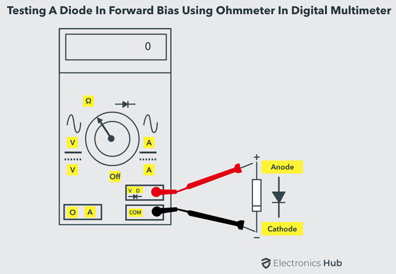
- Keep the Digital multimeter (DMM) in resistance or ohmmeter mode by rotating the central knob or selector to the place where ohm symbol or resistor values are indicated. Keep the selector in low resistance (may be 1K ohm) mode for forward-bias and keep it in high resistance mode (100K ohm) for the reverse bias testing procedure.
- Connect the red probe to the anode and black probe to the cathode. This means diode is forward-biased. When the diode is forward-biased, the resistance of the diode is so small.
If the meter displays a moderately low value on the meter display i.e., a few tens of ohms, then the diode is not good. But if the resistance reading is few hundred ohms to few kilo ohms, then the diode is good and working properly.
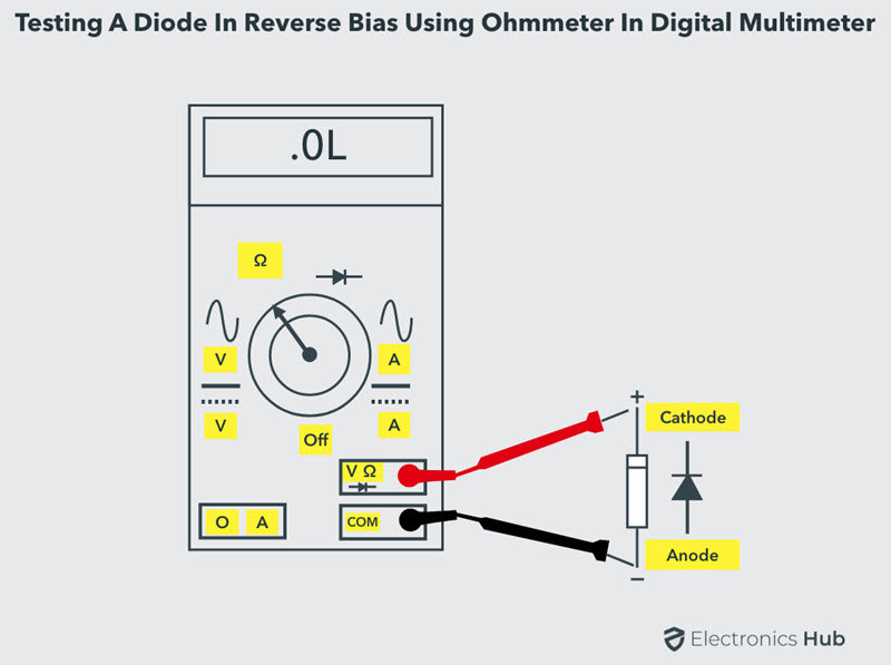
- Now reverse the terminals of the multimeter such that anode is connected to black probe and cathode to red probe. So the diode is reverse biased.
- If the meter shows a very high resistance value or OL on meter display, then the diode is good and functions properly. Since in reverse biased condition diode offers a very high resistance.
From the above it is clear that for proper working of the diode, DMM should read some low resistance in the forward-biased condition and a very high resistance or OL in reverse-biased condition.
If the meter indicates a very high resistance or OL in both forward and reverse-biased conditions, then the diode is said to be opened. In other hand, if the meter reads a very low resistance in both directions, then the diode is said to be shorted.
How to Test a Diode using Analog Multimeter?
Most analog multimeters usually do not have a dedicated Diode Test Mode. So, we will be using the Resistance Mode in Analog Multimeter, which is similar to the testing of diode using DMM ohmmeter mode.

- Keep the multimeter selector switch in low resistance value
- Connect the diode in the forward-biased condition by connecting the positive terminal to anode and negative to the cathode.
- If the meter indicates a low resistance value, then it says that the diode is healthy.
- Now put the selector in high resistance position and reverse the terminals of the meter by connecting positive to the cathode and negative to anode. In this case, the diode is said to be in reverse bias.
- If the meter indicates OL or a very high resistance, then it refers to the perfect condition of the diode.
- If the meter fails to show above readings, then the diode is said to be defective or bad.
This is about simple PN diode-testing using digital and analog multimeters. These testing procedure may not be applicable for all types of diodes. So, now let us see how to test an LED and a Zener diode.
How to Test LED (Light Emitting Diode)?
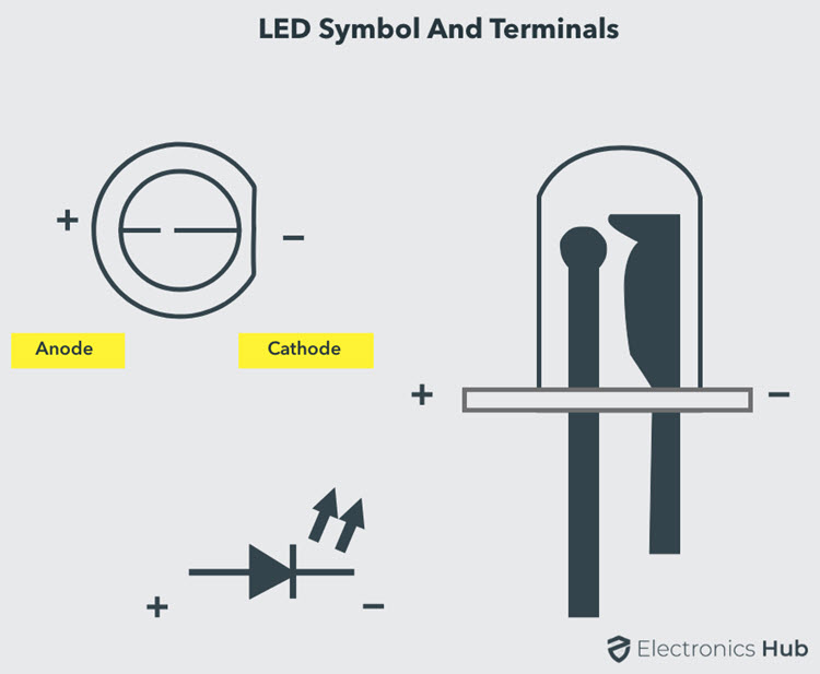
As discussed above, before testing any diode we must know its pins (terminals). The terminals of the LED can be identified by the length of the leads. Longer one is anode and the shorter one is the cathode. Also, another method is using the surface structure wherein a flat surface indicates the cathode and other one is the anode.
Let us now see how to test an LED using a digital multimeter.
- Identify the anode and cathode terminals of the LED.
- Place the multimeter selector / knob in diode mode.
- Connect the probes of the meter to LED such that it is forward-biased.
- If the LED is working properly, then it glows otherwise the LED is defective.
- Reverse-biased testing cannot be possible with LED since it doesn’t work in reverse-biased condition.
How to Test a Zener Diode?
When compared to the testing a normal diode, testing a Zener diode needs some extra circuitry. Because, the Zener diode conducts in reverse-biased condition and only if the applied reverse voltage is more than the Zener breakdown voltage.
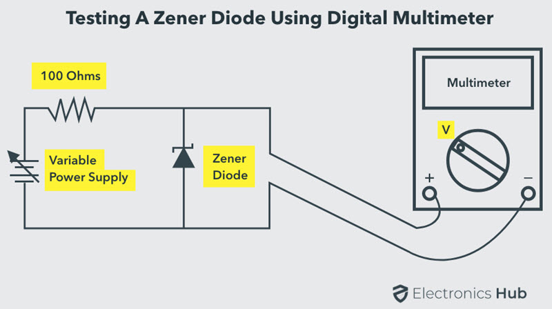
- Identify the terminals anode and cathode of the Zener diode and its identification process is similar to the normal PN diode (using a mark).
- Connect the test circuit as shown in the above figure.
- Place the multimeter knob in voltage mode.
- Connect the meter probes across the Zener diode as shown in figure.
- Gradually increase the input supply to the diode, and observe the voltage on the meter display. This reading on the meter must be such that as we increase the variable supply, meter output should increase until the breakdown voltage of the diode. And beyond this point meter should show a constant value of voltage irrespective of any increase of the input variable supply. If it so, then Zener diode is healthy, otherwise defective.
Suppose, if we apply a 12V to the Zener diode (with a breakdown voltage is 6V) from the battery through a resistor, then multimeter must show a reading which is approximately equal to the 6V, if the Zener diode is healthy.
Conclusion
A complete beginner’s guide on how to test a diode. Learn how to identify the terminals of a Diode, test a diode with Digital Multimeter (DMM), Analog Multimeter, test LEDs and Zener Diodes.

6 Responses
pls, i want to be a circuit builder, therefore i need a mentor to help me out
Hello, did you find a mentor? …. 🙂
Hello john,,, If your idea was to help… I would really be interested
Its very helpful and thank you for that complete details. I have a question how to test a transistor? Thank for the feedback. God bless
Very good axplanation about diode testing DMM & AMM meters. Its very helpful Thanks.
Best ever explanation on diodes 👍