A gate is the functional logic device which operates on input signals. Logic gates are the primary devices or basic elements for logic device design. It performs logical operation based on the input signals. Examples for logic gates are NAND, NOR, AND, OR, EX – OR, NOT and BUFFER.
In our previous tutorials we learnt about Logic buffer and logic inverter. Now we have a tutorial on Logic OR gate.
OR Gate
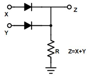
The circuit design of OR gate (by using diodes) is given below. The circuit uses two diodes at input side. In all logic circuits, +5 volts is represented as HIGH level logic and 0 volts or ground is represented as the LOW level logic. The two logic levels are represented as binary numbers 0 and 1.
Here 0 means low (switch is at OFF position) and 1 means high (switch is at ON position). The OR gate produces low output only when both the inputs are low, in all other conditions or for all other combinations of inputs , the output of OR gate will be high.
If we connect HIGH logic level voltage i.e. +5 volts to any one of the input, then the diode becomes forward biased and that makes the output to be high. Or if we connect high level voltage to both inputs, then both the inputs will be high making the diodes to be in forward bias condition.
Then the OR circuit output will be HIGH. If the two inputs of the OR gate are low, then the inputs diodes become reverse biased, allowing no current to flow in the circuit. So the output will be LOW (0).
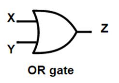
OR gate Logic Symbol and Boolean expression
The OR gate is logically represented as shown below with two inputs and one outputs.
Boolean expression
The mathematical functioning of OR gate is given as Z = X + Y. Here X and Y are the inputs and Z is the output of OR gate.
Truth table
The truth table for logical OR gate is given below.
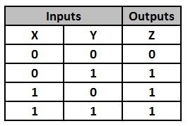
This shows us that the output put of OR gate will be high with all combinations of inputs except for both low inputs condition.
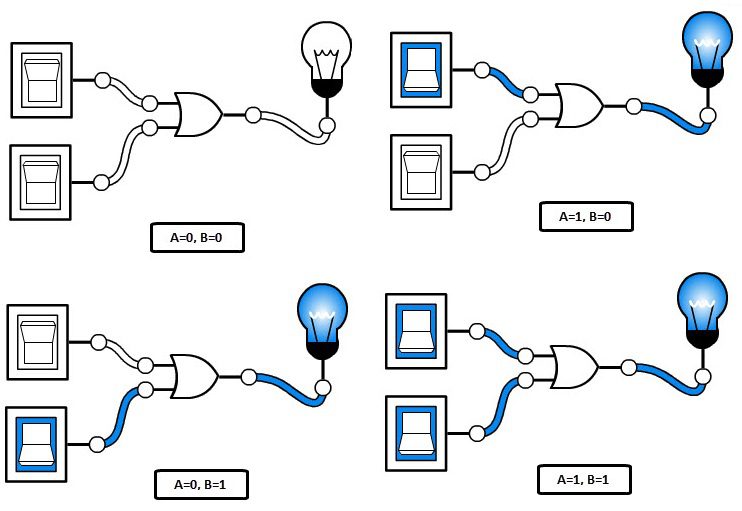
Explanation of OR gate with light switch circuit
The OR gate switching circuit will have two inputs connected to two manually toggled switches. Let the two switches be A and B, then the we can explain the switching operation of OR gate as
- When both switches A and B are open (switches are supplied with low level input signal) i.e. A=0, B=0, then the bulb will not glow.
- When switch A is close (supplied with high level input signal) and B is open (supplied with low level input signal) i.e. A=1, B=0, then the bulb will glow.
- When switch A is open (supplied with low level input signal) and B is close (supplied with high level input signal) i.e. A=0, B=1, then the bulb will glow.
- When both switches A and B are close (switches are supplied with high level input signal) i.e. A=1, B=1, then the bulb will glow.
Pulsed operation
Let’s apply two different clock signals to both the inputs of OR logic gate A and B, then if we observe the output of the OR gate it will be as shown below.
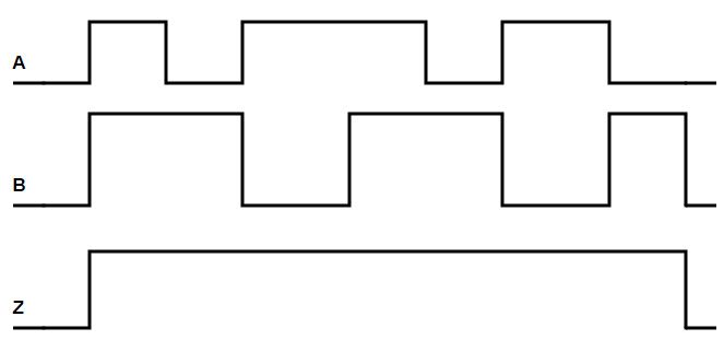
When the two inputs are high, then the output is also high. And further even when either of the inputs is high, then the output of OR gates continued to be high state. When both the inputs of the OR gate are at low level, then the output also comes to low level.
OR gate using NPN transistors
We can construct an OR gate by using diodes as well as transistors also. OR gate designed using NPN transistor is shown in the below diagram.
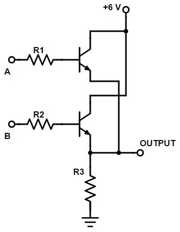
+6 volts voltage is supplied to collectors of transistors to drive the circuit and inputs are applied to the transistor through a resistor. Emitter of second transistor is connected to ground. The output is calculated at the emitter of the transistors.
For OR logic circuit, the transistors are connected in parallel and the output of the circuit is measured HIGH when both the transistors conducting or if any one of the transistors is conducting.
3-Input OR gate
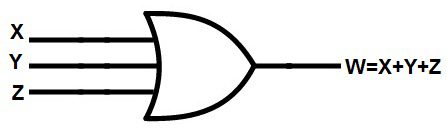
We can design an OR gate with 3 inputs also. Though the OR gate have 3 inputs, the Boolean equation will not change. Th output of the OR gate is equal to the sum of the inputs.
3-Input OR gate symbol
Truth table
The truth table of 3 –input OR gate is given below
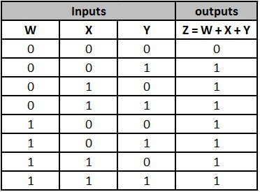
The output of the 3 input OR gate is low when all the 3 inputs are low and it will be high for all other combinations of inputs.
Multi-input OR Gate
We can design multiple input OR gate by connecting logic gates externally to an OR gate. The multiple input OR gate is shown below.
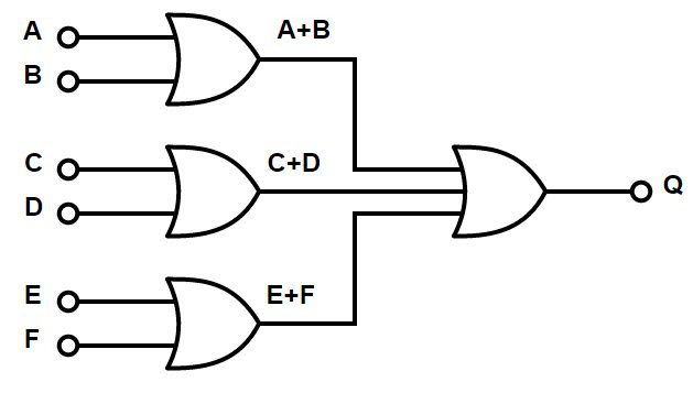
The Boolean expression of 6 input OR gate is Q = (A + B) + (C + D) + (E + F) . If we need to design an odd input OR gate , then we make some inputs as “unused” by connecting them directly to the ground by pull down resistors.
Commonly available TTL and CMOS logic OR gate IC’s
The most commonly (widely) used OR gate ICs are listed below.
TTL Logic OR Gates  74LS32 Quad 2-input
CMOS Logic OR Gates CD4071 Quad 2-input
CD4075 Triple 3-input
CD4072 Dual 4-input
Hex 2-input OR drivers 74832
All available OR logic gate ICs are tabulated below
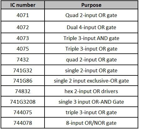
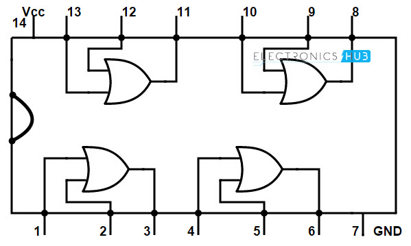
7432 Quad 2-input OR Gate IC
The 74 series IC is used as Quad 2 input OR gate. The IC diagram of 7432 is shown below.
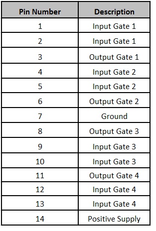
Pin description or 7432 OR gate IC
OR gate Applications
OR gate is used in many of our real life applications. One of its applications, “Alarm circuit for car door system” is explained below.
We design this alarm by connecting four circuits to the 4 doors of the car (or any vehicle) when the door is open, the circuit generates high output (Logic 1) and similarly when the door is closed, the circuit generates 0 (Logic 0). The 4 outputs of four doors are connected to a 4 –input OR gate, which output is connected to an alarm.
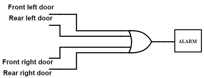
When any one or more doors are opened, then the output of the 4- input OR gate is 1, then the alarm rings. So that we can know the condition of doors, whether they are properly closed or not.
