Data comparison is needed in digital systems while performing arithmetic or logical operations. This comparison determines whether one number is greater than, equal, or less than the other number. A digital comparator is widely used in combinational system and is specially designed to compare the relative magnitudes of binary numbers.
These are also available in IC form with different bit comparing configurations such as 4-bit, 8-bit, etc. More than one comparator can also be connected in cascade arrangement to perform comparison of numbers of longer lengths.Whenever we want to compare the two binary numbers, first we have to compare the most significant bits.
If these MSBs are equal, then only we need to compare the next significant bits. But if the MSBs are not equal, then it would be clear that either A is greater than or less than B and the process of comparison ceases.
For example, the two 2-bit number are A = A1A0 and B=B1B0. If A1 is not equal to B1, then it is clear that A is greater than B for A1 =1 & B1= 0 or else A is less than B for A0= 0 & B0 =1. At this stage the process of comparison ceases.
If the MSBs are equal, i.e., A1=B1 only then we need to compare the next significant bits A0 and B0 and decide whether the number is greater than, less than or equal. So, the comparator produces three outputs as L, E and G corresponds to less than, equal and greater than comparisons.
Types of Digital Comparators
Digital comparators can be of two types
Identity Comparator
Comparators that have only one output terminal and produces the output either low or high are identity comparators.
Magnitude Comparator
Comparators with three output terminals and checks for three conditions i.e greater than or less than or equal to is magnitude comparator.
Digital Comparator
A magnitude digital comparator is a combinational circuit that compares two digital or binary numbers (consider A and B) and determines their relative magnitudes in order to find out whether one number is equal, less than or greater than the other digital number.
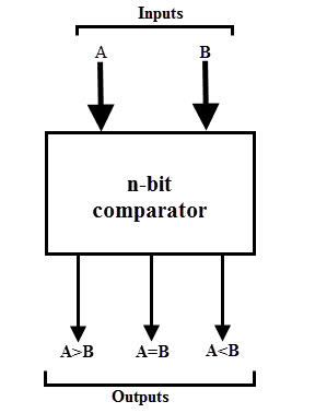
Three binary variables are used to indicate the outcome of the comparison as A>B, A<B, or A=B. The below figure shows the block diagram of a n-bit comparator which compares the two numbers of n-bit length and generates their relation between themselves.
These comparators can compare 2-bit, 4-bit and 8-bit numbers depending on the application requirement. These are available in TTL as well as CMOS logic family ICs and some of these ICs include IC 7485 (4-bit comparator), IC 4585 (4-bit comparator in CMOS family) and IC 74AS885 (8-bit comparator).
Single Bit Magnitude Comparator
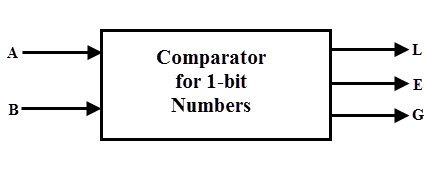
A comparator used to compare two bits, i.e., two numbers each of single bit is called a single bit comparator. It consists of two inputs for allowing two single bit numbers and three outputs to generate less than, equal and greater than comparison outputs.
The figure below shows the block diagram of a single bit magnitude comparator. This comparator compares the two bits and produces one of the 3 outputs as L (A<B), E (A=B) and G (A>B).
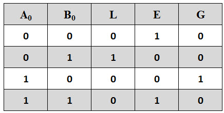
The truth table for the single bit comparator is given below. When A0 B0 = 00 & 11, both inputs are equal, therefore A=B output will be high. When A0 B0 = 01, B is more than A and hence AB is active.
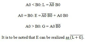
From the truth table logical expressions for each output can be expressed as
By using these Boolean expressions, we can implement a logic circuit for this comparator using two AND gates, one NOT gate and one Ex-NOR gate as shown in below figure. AND gates are used to find whether a binary digit is less than greater than another bit whereas Ex-NOR gate is used to find whether two binary numbers are equal or not.
In the figure, one AND gate has inputs of A0 (B0) ̅ and another has inputs (A0) ̅ B0. Therefore, one AND gate output is 1 if A0 > B0 (i.e., A0 =1 and B0 =0) and is zero if A0 < B0 (i.e., A0 =0 and B0 =1). Similarly, other AND gate output is one if A0 < B0 (i.e., A0 =0 and B0 =1) and is zero if A0 > B0 (i.e., A0 =1and B0 =0).
The Ex-NOR gate has inputs A0 B0, hence the output of the Ex-NOR gate will be 1 if A0 = B0 and the output will be 0 if A0 is not equal to B0.
2-Bit Comparator
A 2-bit comparator compares two binary numbers, each of two bits and produces their relation such as one number is equal or greater than or less than the other. The figure below shows the block diagram of a two-bit comparator which has four inputs and three outputs.
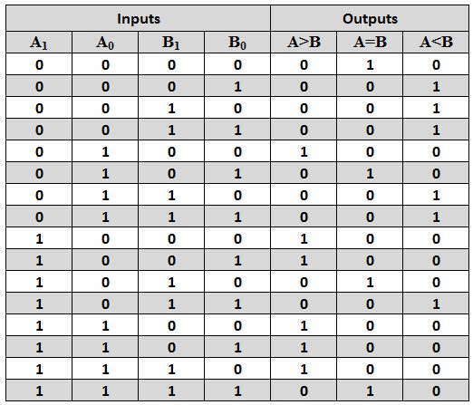
The first number A is designated as A = A1A0 and the second number is designated as B = B1B0. This comparator produces three outputs as G (G = 1 if A>B), E (E = 1, if A = B) and L (L = 1 if A<B).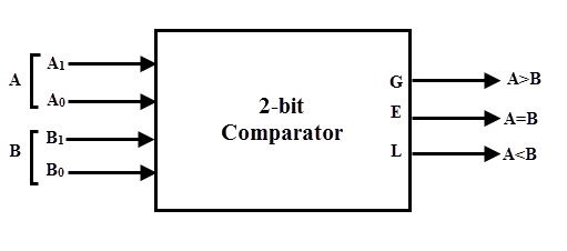 The truth table of this comparator is shown below which depicting various input and output states.
The k-map simplification for the above truth table is as follows.
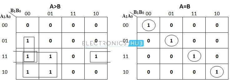
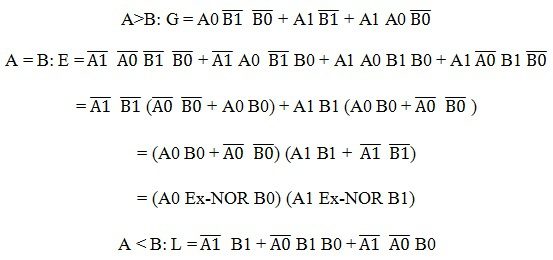
From the above k-map simplification, each output can be expressed as
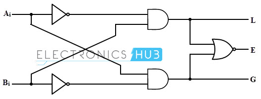
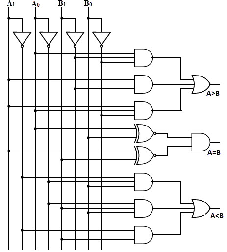
By using above obtained Boolean equation for each output, the logic diagram can be implemented by using four NOT gates, seven AND gates, two OR gates and two Ex-NOR gates.
The figure below shows the logic diagram of a 2-bit comparator using basic logic gates. It is also possible to construct this comparator by cascading of two 1-bit comparators.
4-Bit Comparator
It can be used to compare two four-bit words. The two 4-bit numbers are A = A3 A2 A1 A0 and B3 B2 B1 B0 where A3 and B3 are the most significant bits.
It compares each of these bits in one number with bits in that of other number and produces one of the following outputs as A = B, A < B and A>B. The output logic statements of this converter are
- If A3 = 1 and B3 = 0, then A is greater than B (A>B). Or
- If A3 and B3 are equal, and if A2 = 1 and B2 = 0, then A > B. Or
- If A3 and B3 are equal & A2 and B2 are equal, and if A1 = 1, and B1 = 0, then A>B. Or
- If A3 and B3 are equal, A2 and B2 are equal and A1 and B1 are equal, and if A0 = 1 and B0 = 0, then A > B.
From the above statements, the output A > B logic expression can be written as
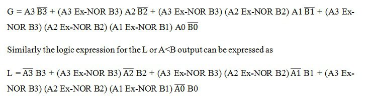 The equal output is produced when all the individual bits of one number are exactly coincides with corresponding bits of another number. Then the logical expression for A=B output can be written as
E = (A3 Ex-NOR B3) (A2 Ex-NOR B2) (A1 Ex-NOR B1) (A0 Ex-NOR B0)
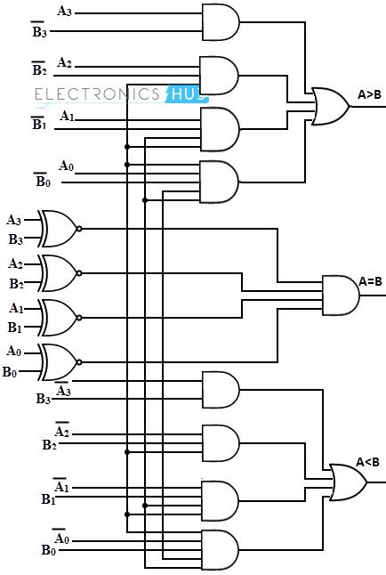
From the above output Boolean expressions, the logic circuit for this comparator can be implemented by using logic gates as given below. In this the four outputs from Ex-NOR gates are applied to AND gate to give the binary variable E or A = B. The other two outputs are also use Ex-NOR outputs to generate the Boolean functions as shown figure.
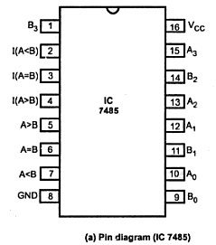
The 4-bit comparator is mostly available in IC form and common type of this IC is 7485. This IC can be used to compare two 4-bit binary words by grounding I (A>B), I (A<B) and I (A=B) connector inputs to Vcc terminal. The figure below shows the pin diagram of IC7485 comparator.
In addition to the normal comparator, this IC is provided with cascading inputs in order to facilitate the cascading several comparators. Any number of bits can be compared by cascading several of these comparator ICs.
8-Bit Comparator
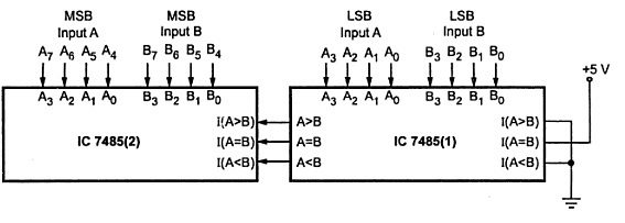
An 8-bit comparator compares the two 8-bit numbers by cascading of two 4-bit comparators. The circuit connection of this comparator is shown below in which the lower order comparator A<B, A=B and A>B outputs are connected to the respective cascade inputs of the higher order comparator.
For the lower order comparator, the A=B cascade input must be connected High, while the other two cascading inputs A ,B must be connected to LOW. The outputs of the higher order comparator become the outputs of this eight-bit comparator.
Applications of Comparators
- These are used in the address decoding circuitry in computers and microprocessor based devices to select a specific input/output device for the storage of data.
- These are used in control applications in which the binary numbers representing physical variables such as temperature, position, etc. are compared with a reference value. Then the outputs from the comparator are used to drive the actuators so as to make the physical variables closest to the set or reference value.
- Process controllers
- Servo-motor control

14 Responses
These answers are really helpful.
can u plz explain this relation:
E= (L+G)’.why u not simply use AxnorB for E in 1 bit comparator ??
Very informative…
Can I make a project in this magnitude comparator,by glowing LED when AB and using 5v power supply (4-bit magnitude comparator).
Hi. thanks a lot. just one correction is needed I think: in the “Single Bit Magnitude Comparator” section the NOR gate is being used in the graphic but the article says XNOR instead.
thanks again. really helpful.
really helpful
Thats really helpful
over all v.v.v best & informative but
E=(L+G) ????????????
Can you please help me to solve/ design 16 bit comparator.
Which all gates need to be added to cascade two 8bit comparators ???
i want to desing 5 bit comparotor using tw0 4 bit comparotor ic 7485 plz help me
I want to make experiment to compare 6 bit numbers using IC 7485 please reply to this request immediately
Thanj a lot
This is helpful
Kindly solve that Question
Q. compare 2, 4 bit binary number obtain in part using a magnitude compactor, Name one number as A and other as B
Really helpful