A BCD (Binary Coded Decimal) or Decade Counter circuit is an essential component in digital electronics, designed to count from 0 to 9 sequentially in binary form, representing each decimal digit. Let us understand more about it.
BCD or Decade Counter Circuit
A binary coded decimal (BCD) is a serial digital counter that counts ten digits .And it resets for every new clock input. As it can go through 10 unique combinations of output, it is also called as “Decade counter”. A BCD counter can count 0000, 0001, 0010, 1000, 1001, 1010, 1011, 1110, 1111, 0000, and 0001 and so on.
A 4 bit binary counter will act as decade counter by skipping any six outputs out of the 16 (24) outputs. There are some available ICs for decade counters which we can readily use in our circuit, like 74LS90. It is an asynchronous decade counter.
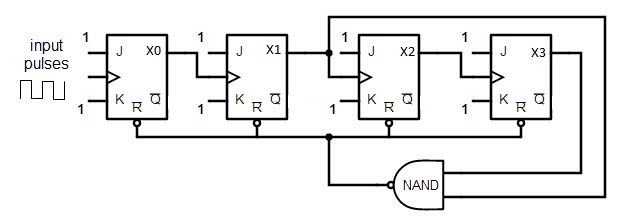
The above figure shows a decade counter constructed with JK flip flop. The J output and K outputs are connected to logic 1. The clock input of every flip flop is connected to the output of next flip flop, except the last one.
The output of the NAND gate is connected in parallel to the clear input ‘CLR’ to all the flip flops. This ripple counter can count up to 16 i.e. 24.
Decade Counter Operation
When the Decade counter is at REST, the count is equal to 0000. This is first stage of the counter cycle. When we connect a clock signal input to the counter circuit, then the circuit will count the binary sequence. The first clock pulse can make the circuit to count up to 9 (1001). The next clock pulse advances to count 10 (1010).
Then the ports X1 and X3 will be high. As we know that for high inputs, the NAND gate output will be low. The NAND gate output is connected to clear input, so it resets all the flip flop stages in decade counter. This means the pulse after count 9 will again start the count from count 0.
Truth Table of Decade Counter
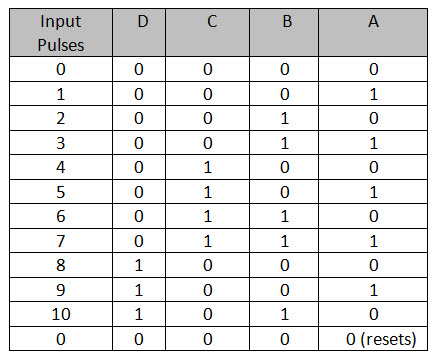
The above table describes the counting operation of Decade counter. It represents the count of circuit for decimal count of input pulses. The NAND gate output is zero when the count reaches 10 (1010).
The count is decoded by the inputs of NAND gate X1 and X3. After count 10, the logic gate NAND will trigger its output from 1 to 0, and it resets all flip flops.
State Diagram of Decade Counter
The state diagram of Decade counter is given below.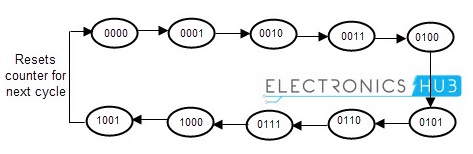 If we observe the decade counter circuit diagram, there are four stages in it, in which each stage has single flip flop in it. So it is capable of counting 16 bits or 16 potential states, in which only 10 are used. The count starts from 0000 (zero) to 1001 (9) and then the NAND gate will reset the circuit.
Multiple counters are connected in series, to count up to any desired number. The number that a counter circuit can count is called “Mod” or “Modulus”. If a counter resets itself after counting n bits is called “Mod- n counter” “Modulo- n counter”, where n is an integer.
The Mod n counter can calculate from 0 to 2n-1. There are several types of counters available, like Mod 4 counter, Mod 8 counter, Mod 16 counter and Mod 5 counters etc.
Commonly available Decade counter IC’s
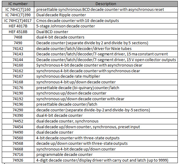
4017B and 7049 are the most used ICs to design a decade counter. The other commonly available integrated circuits (ICs) for Decade counter and their purposes are listed below.
74LS90 decade counter IC description
The IC 74LS90 is one most used chip we use to design decade counter.
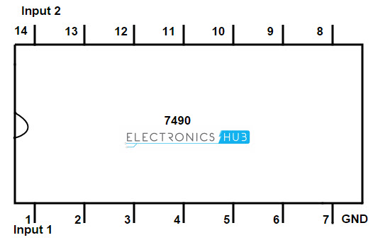
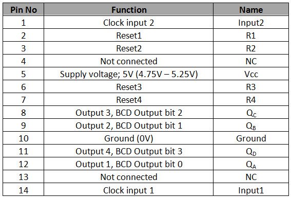
Pin configuration
Explanation
It is a simple counter which can count from 0 – 9. As it is a 4 bit binary decade counter, it has 4 output ports QA, QB, QC and QD. When the count reaches 10, the binary output is reset to 0 (0000), every time and another pulse starts at pin number 9. The Mod of the IC 7490 is set by changing the RESET pins R1, R2, R3, R4.
If any one of R1 & R2 is at high or R3 & R4 are at ground, the counter will reset all the outputs QA, QB, QC and QD to 0. If the pins R3 & R4 are high, then the count on QA, QB, QC and QD is 1001.
As we studied earlier, we can increase the counting capability of a Decade number by connecting more ICs n series; we can count 99 with two 7490 ICs connected in series. This 7490 IC has inbuilt Divide by 2 and Divide by 5 counters in it.
It can also be used as divide by 10 counter by connecting by connecting clock input 2 and QA and connecting all rest pins to ground and giving pulse input to 1. It is used as divide by 6 counter by supplying pulse at input 1 and grounding reset pins R3 and R4 and connecting QA with input 2.
7490 IC can work like bi –quinary counter, which is used to store decimal digits in the form of 4 bit binary numbers.
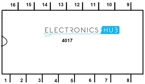
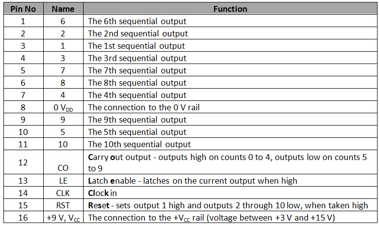
4017 CMOS decade counter IC description
Applications of BCD Counter or Decade Counters
The key advantages and benefits if BCD counters are
- Clock generation
- Clock division
- Integrated oscillator
- Low power cmos
- TTL compatible inputs
- In frequency counting circuits
Decade counter in Frequency Counting
Binary counters can be used to design frequency counters. The circuit design for frequency counter is given below by using decade counter (designed by JK flip flops).
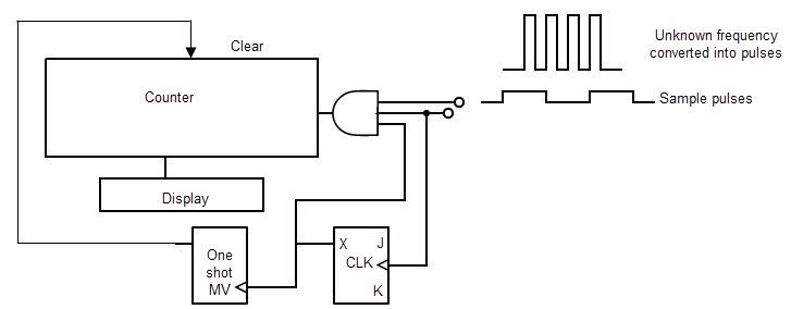
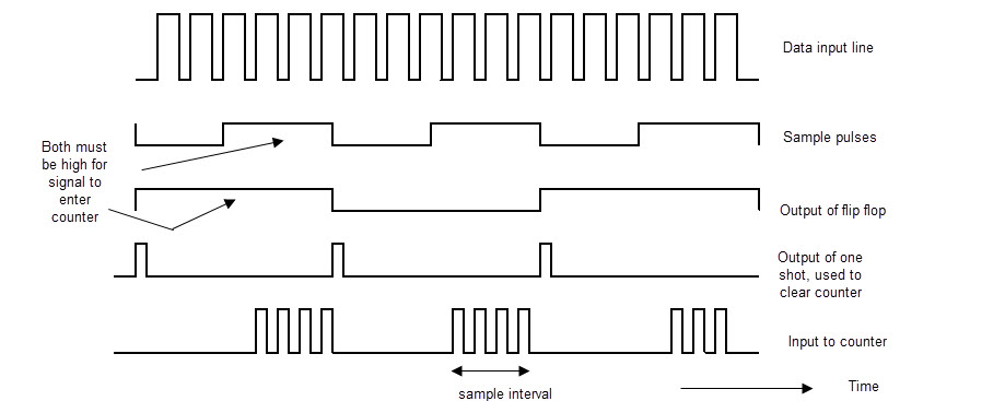
To count the frequency of the unknown counter, e fed the unknown frequency to one inputs and sample pulses to another input of AND gate. When the sample pulses are at high level, the input signal is allowed to transfer to the counter, otherwise it is not allowed for low level sample pulse input.
The frequency of the unknown signal is given by the number of counts divided by sample time interval. The third input of AND gate is given by a JK flip flop, to hold the produced output or result of the counter.
When the input from JK flip flop and sample pulse both are high, then the output reaches the counter. The counter will reset by a one shot multivibrator for each positive going edge of JK flip flop, by sending a pulse to it.

6 Responses
explanation is good but you can’t provide exact circuit diagram
Thank you for this tutorial, just I want to say that there are other integrated decade counters for example CD4026B.
what if we give clock pulse to input 2 of IC 7490 instead of input 1 and connect QD to input 1?
Tysm
pls suggest me some experiment for digital electronics
using only ics
Why there are 3 jk and 1 rs flip flop is use