A DC Motor is a type of electric motor that converts DC electrical power to mechanical power i.e. a DC supply is converted to rotation or movement. DC motors are one of the commonly used motors in different applications like electronic toys, power tools, portable fans, etc.
DC Motors are further classified in to different types like series, shunt and compound and each type is used in different areas of applications. Some DC motors are also used in Robotic and Industrial applications for their easy control and precision.
Since DC motors are generally associated with small to medium applications, where the system mainly consists of a Microcontroller as the main processing unit, controlling and driving a DC motor is very important. This is because, driving a motor directly using the microcontroller is not advised (sometimes not possible) as the current from the Microcontroller is very small (usually less than 30mA).
In this project, a small DC Motor is controlled with an Arduino and a Motor Driver IC where both the speed of the motor and the direction of rotation are controlled.
DC Motor Control With Arduino
Circuit Diagram
Required Components
- Arduino UNO [Buy Here]
- L293D Motor Driver IC [Buy Here]
- 10KΩ Potentiometer
- Push button X 2
- 12V DC Motor
- 12V DC Adapter
- Connecting wires
Component Description
Arduino UNO
Arduino UNO is a simple electronics prototyping based on ATmega328P Microcontroller. It is an 8-bit AVR based microcontroller that acts as the brain of the Arduino UNO. Arduino UNO boards are frequently used in many entry level applications like controlling LEDs, driving motors to high end applications like weather monitoring, handheld gaming consoles etc.
L293D Motor Driver IC
As the name suggests, L293D is a quadruple H-bridge, high current motor driver IC. It can be used to drive two motors at a time in both the directions with an output current of 600mA for each motor. L293D IC is designed to drive relays, DC motors, stepper motors and other inductive loads with high current and high voltage requirements.
Circuit Design
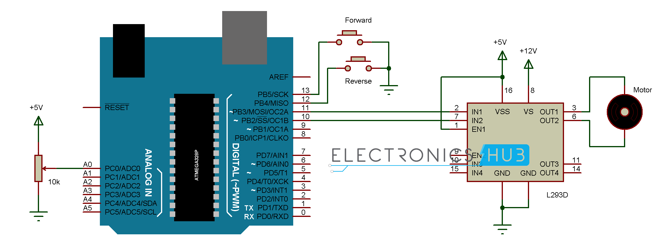
- As mentioned earlier, Arduino UNO and L293D Motor Driver IC are the main components of the circuit. Arduino UNO acts as the main processing part of the circuit. A button and a potentiometer are used to control the direction of rotation and speed of the motor respectively.
- Hence, a button is connected to Pin 13 of Arduino for driving the motor in forward direction and another button is connected to Pin 12 of Arduino for driving the motor in reverse direction with the other terminals of both the buttons connected to ground.
- A potentiometer i.e. the wiper terminal of the pot is connected to analog input pin A0 of the Arduino UNO. The other terminals of the potentiometer are connected to 5V supply and ground respectively.
- L293D is a 16-pin IC available in dual in-line package. As it is capable of driving two motors, we’ll see the connections that are needed for driving a single motor. In that,
- Pin 1 of L293D IC is used to enable the driver channels 1 and 2 i.e. inputs of motor 1. It is an active high pin and hence it is connected to 5V supply.
- Pins 2 and 7 of L293D are inputs of drivers associated with motor 1. They are connected to Pins 11 and 10 of Arduino UNO respectively.
- Pins 3 and 6 of L293D are the output pins of first driver channel. They must be connected to the motor we are going to control.
- Pins 4, 5, 12 and 13 of the L293D IC are ground pins.
- The remaining connections with respect to L293D IC are the power supply pins. L293D Motor Driver IC needs two types of power: one for its internal operations and other for driver channels that drive the motor.
- Pin 16 of L293D IC is the supply pin for internal operations and is connected to a 5V supply. Pin 8 of L293D IC is the supply for driving the motor and is connected to a 12V supply.

Working Process
The aim of this project is to design an Arduino based system for controlling a DC Motor. All the connections are made as per the circuit diagram mentioned above. The working of the project is very simple and is explained here.
Two buttons are used in this project, one each for forward and reverse direction of the motor. The two buttons are connected to Pins 13 and 12 of Arduino which are internally pulled-up (using code). The other terminals of the buttons are connected to ground and hence when the button is pressed, the microcontroller detects LOW (logic 0).
The output of the POT is an analog signal and hence it is connected to analog pin of the Arduino. Based on the analog voltage value from the POT, the speed of the motor is varied.
For this to happen, we need to use the concept of PWM in the circuit. The inputs to the motor driver IC must be in the form of a PWM signal and hence are connected to Pins 11 and 10 of Arduino respectively, which are capable of generating PWM signals.
When the system is powered ON, Arduino waits for the button to be pressed. If the forward direction button is pressed, the Arduino drives input 1 of motor driver IC (Pin 2) with PWM signal and a logic low to input 2 (Pin 3). Hence, the motor starts rotating in forward direction.
Similarly, if the reverse direction button is pressed, Arduino drives input 2 (Pin 3) of L293D Motor Driver IC with the PWM signal and input 1 (pin 2) of L293D is given a logic low. Hence, the motor starts rotating in reverse directions.
The speed of the motor in either direction can be controlled using the POT as it controls the duty cycle of the output PWM signal.
Applications
- This circuit, where a DC motor is controlled using an Arduino UNO, can be used in applications like Arduino based robots, speed as well as direction control of DC motors, etc.
- The circuit shown here controls a single DC motor but can be extended to control two motors with independent speed and direction controls.
Code
Recommended Readings:

17 Responses
Sir please tell me if i can use this for 12v 5A dc motor ??
Please reply ASAP.
No L293d cannot drive 5A dc motor.
this project will good and output will come nice project
Sir can we use geared d.c motor for this
yes, you can.
hi I’m sudharson,I have question here . how can use the momentary push button as a trigger for the rotation. I need the motor to rotate either forward or reverse once I trigger the pushbutton instead of holding the switch ON for rotation.
You need to modify the code.
how to add 16X2 display for it
tell me what is the RPM of 12 V dc motor……….??????????????????????????????
reply fast…..
Around 30K RPM.
It depends upon the gear ratio or the rating of the motor.
sir push button switch speed control slow , middle , high use l298 controller drive two motor coding please give mi
hey, helpful code
can you tell me how you calculate motorValue?
I run it on my arduino but there is problem of getting potvalue
its changing form 500 to 600 only
thanks for your good project and i impliment it and working good but how can i control a dc motor in four quadrants ?
const int pin1 = 11;
const int pin2 = 10;
can i use other pin , to the motor driver
Sir i want to do a project on four quadrant speed control of dc motor using arduino + LCD display….sir can you provide me a code and circuit diagram
Sir its not working, actually i used 5v dc motor with 6v dc supply as external…will it work or not…reply fast sir