Basically, cyclo-converters are AC to AC converters and are used to vary the frequency of a supply to a desired load frequency. These are naturally commutated, direct frequency converters that use naturally commutated thyristors. These are mainly used in high power applications up to tens of megawatts for frequency reduction.
Some of the applications of cyclo-converter include high power AC drives, propulsion systems, high frequency induction heating, synchronous motors in sea and undersea vehicles, electromagnetic launchers, etc. Let us discuss this concept in detail.
Introduction to Cyclo-Converters
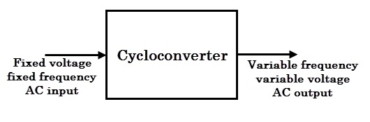
The cyclo-converter is a device that converts AC power of certain frequency to AC power of another frequency (usually lower frequency).
It converts the frequency without help of any intermediate DC link. The output voltage and frequency of a cyclo-converter can be varied continuously and independently using a control circuit. Therefore, unlike other converters, it is a single stage frequency converter.
Cyclo-converters are constructed using naturally commutated thyristors with inherent capability of bidirectional power flow. These can be single phase to single phase, single phase to three- phase and three-phase to three phase converters.
So the control circuit implementation is not simple because large number of SCRs, typically 4 or 8 SCRs for single phase and 36 for three- phase supply. For such controller, a microcontroller or microprocessor or DSP is used to trigger SCRs.
Basically, these are divided into two main types, and are given below.
Step-down cyclo-converter
It acts like a step-down transformer that provides the output frequency less than that of input, fo < fi.
Step-up cyclo-converter
It provides the output frequency more than that of input, fo > fi.
In case of step-down cyclo-converter, the output frequency is limited to a fraction of input frequency, typically it is below 20Hz in case 50Hz supply frequency. In this case, no separate commutation circuits are needed as SCRs are line commutated devices.
But in case of step-up cyclo-converter, forced commutation circuits are needed to turn OFF SCRs at desired frequency. Such circuits are relatively very complex. Therefore, majority of cyclo-converters are of step-down type that lowers the frequency than input frequency.
Step-down cyclo-converter circuits can be further classified into following types.
- Single-phase to single-phase cyclo-converters
- Three-phase to single-phase cyclo-converters
- Three-phase to three-phase cyclo-converters
Besides the frequency control, cyclo-converter output voltage can be varied by applying phase control technique. These can be used to provide either fixed frequency output from variable frequency input value or variable frequency output from fixed frequency input.
These are mainly used in very high power, low speed AC motors and traction systems, especially low frequency three-phase to single phase systems.
Basic Principle of Operation of Cyclo-converter
The equivalent circuit of a cyclo-converter is shown in figure below. Here each two quadrant phase controlled converter is represented by a voltage source of desired frequency and consider that the output power is generated by the alternating current and voltage at desired frequency.
The diodes connected in series with each voltage source represent the unidirectional conduction of each two quadrant converter. If the output voltage ripples of each converter are neglected, then it becomes ideal and represents the desired output voltage.
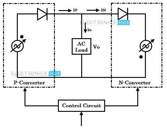
If the firing angles of individual converters are modulated continuously, each converter produces same sinusoidal voltages at its output terminals.
So the voltages produced by these two converters have same phase, voltage and frequency. The average power produced by the cyclo-converter can flow either to or from the output terminals as the load current can flow freely to and from the load through the positive and negative converters.
Therefore, it is possible to operate the loads of any phase angle (or power factor), inductive or capacitive through the cyclo-converter circuit.
Due to the unidirectional property of load current for each converter, it is obvious that positive converter carries positive half-cycle of load current with negative converter remaining in idle during this period.
Similarly, negative converter carries negative half cycle of the load current with positive converter remaining in idle during this period, regardless of the phase of current with respect to voltage.
This means that each converter operates both in rectifying and inverting regions during the period of its associated half cycles.
The figure below shows ideal output current and voltage waveforms of a cyclo-converter for lagging and leading power factor loads. The conduction periods of positive and negative converters are also illustrated in the figure.
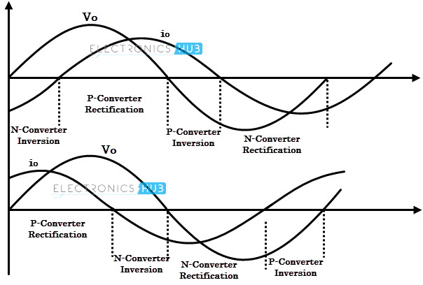
The positive converter operates whenever the load current is positive with negative converter remaining in idle. In the same manner negative converter operates for negative half cycle of load current.
Both rectification and inversion modes of each converter are shown in figure. This desired output voltage is produced by regulating the firing angle to individual converters.
Single-phase to single-phase cyclo-converters
These are rarely used in practice; however, these are required to understand fundamental principle of cyclo-converters.
It consists of two full-wave, fully controlled bridge thyristors, where each bridge has 4 thyristors, and each bridge is connected in opposite direction (back to back) such that both positive and negative voltages can be obtained as shown in figure below. Both these bridges are excited by single phase, 50 Hz AC supply.
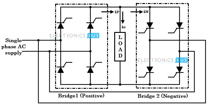
During positive half cycle of the input voltage, positive converter (bridge-1) is turned ON and it supplies the load current. During negative half cycle of the input, negative bridge is turned ON and it supplies load current. Both converters should not conduct together that cause short circuit at the input.
To avoid this, triggering to thyristors of bridge-2 is inhibited during positive half cycle of load current, while triggering is applied to the thyristors of bridge-1 at their gates. During negative half cycle of load current, triggering to positive bridge is inhibited while applying triggering to negative bridge.
By controlling the switching period of thyristors, time periods of both positive and negative half cycles are changed and hence the frequency. This frequency of fundamental output voltage can be easily reduced in steps, i.e., 1/2, 1/3, 1/4 and so on.
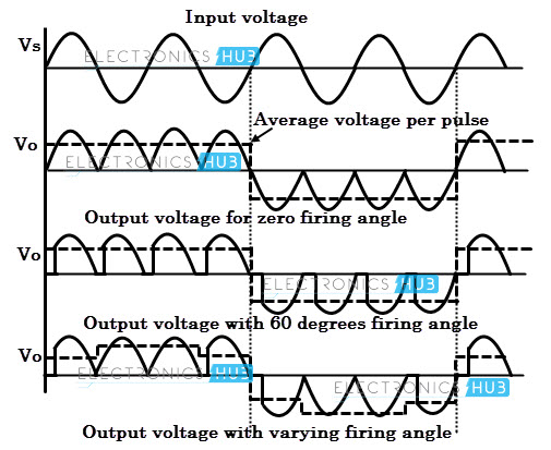
The above figure shows output waveforms of a cyclo-converter that produces one-fourth of the input frequency. Here, for the first two cycles, the positive converter operates and supplies current to the load.
It rectifies the input voltage and produce unidirectional output voltage as we can observe four positive half cycles in the figure. And during next two cycles, the negative converter operates and supplies load current.
Here current waveforms are not shown because it is a resistive load in where current (with less magnitude) exactly follows the voltage.
Here one converter is disabled if another one operates, so there is no circulating current between two converters. Since the discontinuous mode of control scheme is complicated, most cyclo-converters are operates on circulating current mode where continuous current is allowed to flow between the converters with a reactor.
This circulating current type cyclo-converter can be operated on with both purely resistive (R) and inductive (R-L) loads.
Three-phase to single-phase Cyclo-converters
Similar to the above cyclo-converter, a three-phase to single phase cyclo converter also consists of positive and negative group thyristors.
These cyclo-converters can be half-wave or full bridge converters as shown in figure. Like single phase cyclo-converters, these also produce a rectified voltage at the load terminals by each group of thyristors.
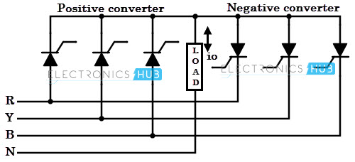
During positive half cycle of the input, conduction of the positive group thyristors is controlled and during negative half-cycle, conduction of negative group of thyristors is controlled in order to produce an output voltage at desired frequency.
In a bridge type of cyclo-converter, both positive and negative converters can generate voltages at either polarity, but negative converter only supplies negative current while positive converter supply positive current.
Therefore, the cyclo-converter can operate in four quadrants, i.e., rectification modes of (+V, +i) and (-V, -i) and inversion modes of (+V, -i) and (-V, +i).
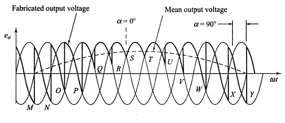
The above figure shows the conversion of three phase supply at one frequency to single phase supply of lower frequency. In this, the firing angle to a positive group of thyristors is varied progressively to produce single phase output voltage.
At point M, the firing angle is 90 degrees and it is reduced till point S where it is zero. Again from point T to Y, the delay angle is progressively increased.
This varied triggering signals to the thyristors, varies its conduction time periods and hence the frequency of the output voltage.
Three-phase to Three-phase Cyclo-converters
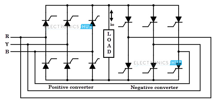
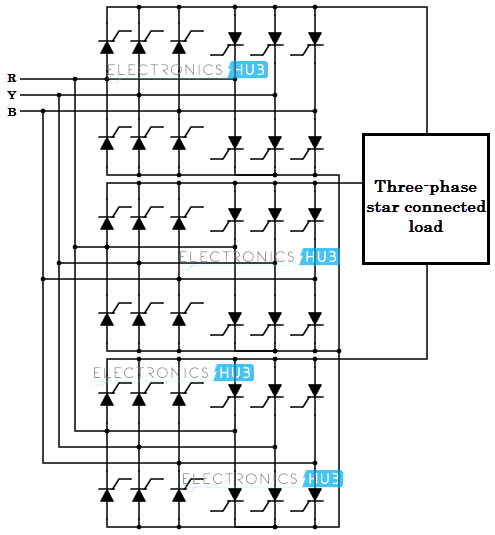
These are obtained by connecting 3 three-phase to single-phase cyclo-converters to the load. These converters can be connected in star or delta. Three phase cyclo-converter of both half-wave and bridge types are shown in figure below.
Three-phase to three-phase cyclo-converter is also called as 18-thyristor cyclo-converter or 3-pulse cyclo-converter and three-phase to three-phase bridge type cyclo-converter is called as 6-pulse cyclo-converter or 36-thyristor cyclo-converter.
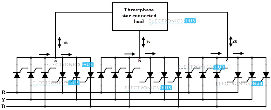
This converter consists of six groups of converter circuits where three groups are called as positive group while other three are negative group.
During each positive half cycle, positive group carries the current and during negative half cycle, negative group carries the current. The duration for conduction of each group of thyristor determines the desired output frequency.
Here average value of output voltage is varied by varying the firing or delay angle of SCRs conduction whereas the output frequency can be varied by changing the sequence of firing the SCRs.
The neutral connection is no longer necessary with a balanced load and hence this connection can be omitted.
Three-phase cyclo converters are more popular than single-phase type as these can handle very large currents and produce smooth output waveform.
It is a highly efficient variable frequency drive, because the pulse number is increased due to the large number of thyristors, which causes small ripple content in the output voltage waveform.
Applications of Cyclo-converters
Cyclo-converters are mainly used for producing low frequency AC voltage. The main application of such requirement is the electric traction system where low frequencies, typically 25 Hz or 16 2/3 Hz are preferred.
In such systems, three-phase squirrel cage induction motor is controlled by a suitable cyclo-converter circuit. Other applications of Cyclo-converter include
- HVDC transmission systems
- Static Var Generation
- Aircraft or shipboard power supplies
- Speed control of high power AC drives
- Grinding mills
- Cement mill drives
- Mine winders
Good to know at the end
The major advantage of cyclo-converter is that it uses a line commutation technique for turning OFF the thyristors, thus it eliminates the need of forced commutation. And these are also more efficient than DC link converters which require two power conversion stages.
But, the major problem with cyclo-converter is that it produces much distorted waveforms for higher frequencies. This can produce reasonable distorted, sinusoidal waveforms up to 16 2/3 Hz, beyond this frequency the wave shapes are not very good.
Also the power factor of the system gets affected when controlling the speed of AC motor using cyclo-converter. It requires a large number of thyristors. In addition, these converters are more costly.
Due to these reasons, cyclo-converters have limited applications. Nowadays, most of the cyclo-converters are being replaced with variable frequency drives.
