After blinking an LED and interfacing a 16 x 2 LCD Display with the Raspberry Pi, the next important project involves Controlling a DC Motor with Raspberry Pi.
By successfully controlling a DC Motor with Raspberry Pi, we can use it in various other applications like Robots, Remote Controlled (RC) Cars, fans and other motor related applications.
The aim of this project is to safely connect a motor to the Raspberry Pi and control it i.e. make it rotate forward or backward.
NOTE: I’ll be using a motor driver in this project which can handle a maximum of two motor. So, there is a provision of controlling two motors individually.
Before proceeding with this project, get an idea about How to setup a Raspberry Pi without Monitor and Keyboard


Controlling a DC Motor with Raspberry Pi
Principle of Operation
The main principle in controlling a DC Motor with Raspberry Pi lies with the Motor Driver. A Motor Driver is a special circuit or IC that provides the necessary power (or rather the current) to the motor for smooth and safe operation.
Even a small 5V DC Motor draws a high initial current of around 300 – 400 mA. This current will then fall down 150 – 200 mA as the motor gains speed to around.
This is a huge current for devices like Microcontrollers, Arduino, Raspberry Pi etc. Hence, we should never connect a motor directly to Raspberry Pi (or any other microcontroller).
Motor Driver play an important role in this situation. They take the control signals from Raspberry Pi and provide the necessary drive current to the motor from the power supply.
In this project, the motor driver (L293D) is given with two control signals from Raspberry Pi through GPIO Pins. As per the Python Program, the motor will rotate in either forward or reverse direction.
Circuit Diagram
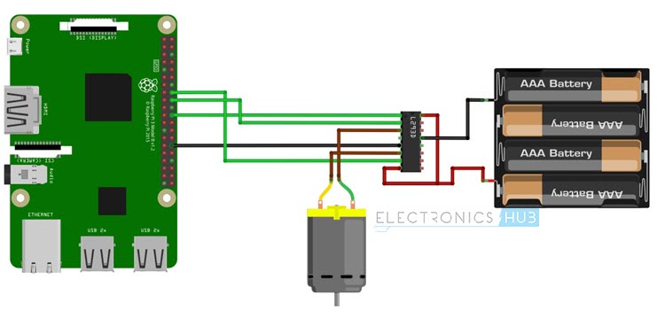
Fritzing Image
As I have said earlier, with L293D Motor Driver IC, we can actually control two motors. For simplicity reasons, I’ll demonstrate the circuit, working and program for controlling a single DC Motor with Raspberry Pi. The following image is the Fritzing diagram of the project.
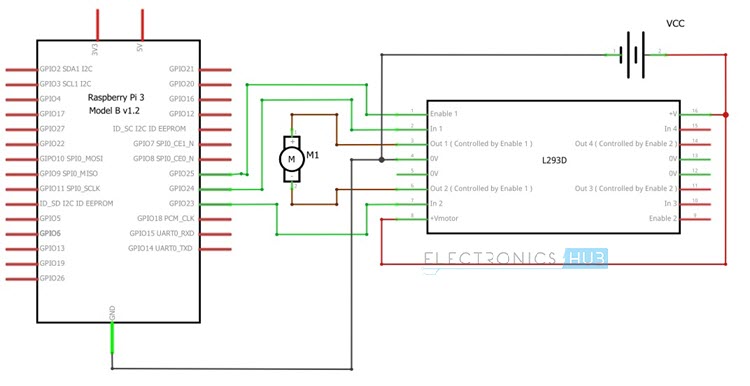
Circuit Diagram
The circuit wiring diagram of the project is shown below. You can easily configure this circuit and the program for controlling two DC Motors with Raspberry Pi and L293D Motor Driver IC.
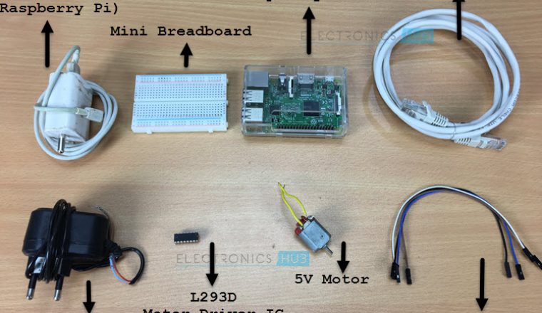
Components Required
- Raspberry Pi 3 Model B
- L293D Motor Driver IC or Module
- Small DC Motor (5V)
- Connecting wires (Jumper Wires)
- 5V – 2A Power Supply for Raspberry Pi
- 5V Supply for Motor
- Miscellaneous (Computer, Ethernet Cable, etc.)
Brief Note on L293D Motor Driver IC
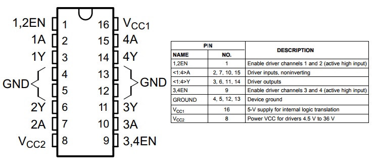
I’ve used L293D Motor Driver IC for controlling a DC Motor with Raspberry Pi. It is a very common motor driver IC which is capable of driving two motors with individual currents up to 600mA.
The Pin diagram of the L293D Motor Driver IC, along with the pin description is shown in the following image.
Circuit Design
The design of the circuit for controlling a DC Motor with Raspberry Pi is very simple. First, connect the pins 8 and 16 (VCC2 and VCC1) of L293D to external 5V supply (assuming you are using a 5V Motor).
There are four ground pins on L293D. Connect pin 4 to the GND of supply. Also, connect the ground pin of L293D to GND pin of the Raspberry Pi.
Finally, we have the enable and control input pins. Connect the pin 1 of L293D (1,2EN) to GPIO25 (Physical Pin 22) of Raspberry Pi. Then connect control input pins 2 and 7 (1A and 2A) to GPIO24 (Physical Pin 18) and GPIO23 (Physical Pin 16) respectively.
OPTIONAL: If you want to connect a second motor, all you need to connect are the Enable (3,4EN) and second motor control inputs (3A and 4A) to three different GPIO Pins of the Raspberry Pi.
Also read this simple project: How to Blink an LED using Raspberry Pi and Python
Python Program for Controlling a DC Motor with Raspberry Pi
Working of the Project and Code Explanation
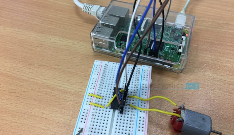
How to Operate the Project?
Before turning on the power supply, make sure that all the connections with respect to motor, power supply and Raspberry Pi are correct. For programming, I’ll be using Python.
Now, open the terminal in Raspberry Pi and create a new Python file as “dcmotorPi.py” using Vim Editor and the following command.
Copy and paste the above program in the editor and the save the file. NOTE: I’ve saved the Python Program in a folder called Python_Progs on the Desktop of Raspberry Pi. Now, in order to run the program, enter the following command in the terminal.
The motor will now rotate in forward direction for 3 seconds, then rotates in reverse direction for 3 seconds and finally stops. After a couple of seconds, the process continues until CRTL+C is pressed in the terminal.
Code Explanation
If you have followed my earlier projects on How to Blink an LED using Raspberry Pi and Interfacing a 16 x 2 LCD with Raspberry Pi, you can easily understand this code.
First, we need to access the GPIO Pins using Python. So, we need import the Module RPi.GPIO in to our program. Similarly, the module time allows us to use its function sleep to pause the program for a predefined time.
Now, I’ve assigned the Pins for L293D Motor Driver IC (Enable and two control inputs). Also, the pin mode is set to GPIO numbering format.
Now, all the pins are declared as outputs. For forward rotation, the enable pin is made HIGH, control input 1A is made HIGH and the other control input 1B is made LOW.
After a delay of three seconds, the control input 1A is made LOW and the control input 1B is made HIGH while keeping the enable pin HIGH. This will rotate the motor in reverse direction.
Finally, after a delay of three seconds, the motor will stop rotating and comes to halt. This process repeats until we press CTRL+C in the terminal.
Applications
- DC Motor are found everywhere: robots, drones, RC Cars, etc. By Controlling a DC Motor with Raspberry Pi, we can develop many motor related projects using Raspberry Pi.
- Can be used in Raspberry Pi based robotic applications like Line Follower Robot, Obstacle Avoiding Robot, Quadcopter, Web Controlled Robot etc.

8 Responses
Hi! I need to handle 5 DC motors with raspberry, just in one direction. Is it possible with L293D?
Yeah it’s possible by editing python code
will this circuit sustain 12V power supply?
No.
Where can I draw that schematic which has Raspberry Pi?
Any software name?
Proteus software
Thanks for the tutorial – worked great!
Hi I have a 12v motor with 12 volt battery How would I connect that would it be the same or different.