Rectifier is an electronic device which coverts the alternating current to unidirectional current, in other words rectifier converts the AC voltage to DC voltage. We use rectifier in almost all the electronic devices mostly in the power supply section to convert the main voltage into DC voltage. Every electronic device will work on the DC voltage supply only.
Rectifiers are classified according to the period of conduction.
They are
- Half Wave Rectifier
- Full Wave Rectifier
You may get detailed information about full wave rectifier in the post: Theory and Working of Full Wave Rectifier. In this session we will see about the working of half wave rectifier and its applications.
Half Wave Rectifier:
The half wave rectifier is a type of rectifier that rectifies only half cycle of the waveform. This article describes the half wave rectifier circuit working. The half rectifier consist a step down transformer, a diode connected to the transformer and a load resistance connected to the cathode end of the diode. The circuit diagram of half wave transformer is shown below:
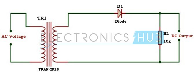
The main supply voltage is given to the transformer which will increase or decrease the voltage and give to the diode. In most of the cases we will decrease the supply voltage by using the step down transformer here also the output of the step down transformer will be in AC. This decreased AC voltage is given to the diode which is connected serial to the secondary winding of the transformer, diode is electronic component which will allow only the forward bias current and will not allow the reverse bias current. From the diode we will get the pulsating DC and give to the load resistance RL.
Working of Half Wave Rectifier:
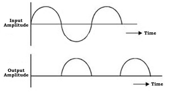
The input given to the rectifier will have both positive and negative cycles. The half rectifier will allow only the positive half cycles and omit the negative half cycles. So first we will see how half wave rectifier works in the positive half cycles.
Positive Half Cycle:
- In the positive half cycles when the input AC power is given to the primary winding of the step down transformer, we will get the decreased voltage at the secondary winding which is given to the diode.
- The diode will allow current flowing in clock wise direction from anode to cathode in the forward bias (diode conduction will take place in forward bias) which will generate only the positive half cycle of the AC.
- The diode will eliminate the variations in the supply and give the pulsating DC voltage to the load resistance RL. We can get the pulsating DC at the Load resistance.
Negative Half Cycle:
- In the negative half cycle the current will flow in the anti-clockwise direction and the diode will go in to the reverse bias. In the reverse bias the diode will not conduct so, no current in flown from anode to cathode, and we cannot get any power at the load resistance.
- Only small amount of reverse current is flown from the diode but this current is almost negligible. And voltage across the load resistance is also zero.
Characteristics of Half Wave Rectifier:
There are some characteristics to the half wave rectifier they are
1. Efficiency: The efficiency is defined as the ratio of input AC to the output DC.
Efficiency, Ƞ = P dc / Pac
DC power delivered to the load, Pdc = I2dc RL = ( Imax/pi ) 2 RL
AC power input to the transformer, Pac = Power dissipated in junction of diode + Power dissipated in load resistance RL
= I2rms RF + I2rms RL = {I2MAX/4}[RF + RL]
Rectification Efficiency, Ƞ = Pdc / Pac = {4/ 2}[RL/ (RF + RL)] = 0.406/{1+ RF/RL }
If RF is neglected, the efficiency of half wave rectifier is 40.6%.
2. Ripple factor: It is defined as the amount of AC content in the output DC. It nothing but amount of AC noise in the output DC. Less the ripple factor, performance of the rectifier is more. The ripple factor of half wave rectifier is about 1.21 (full wave rectifier has about 0.48). It can be calculated as follows:
The effective value of the load current I is given as sum of the rms values of harmonic currents I1, I2, I3, I4 and DC current Idc.
I2 =I2dc+I21+I22+I24 = I2dc +I2ac
Ripple factor, is given as γ = I ac / Idc = (I2 – I2dc) / Idc = {( I rms / Idc2)-1} = Kf2 – 1)
Where Kf is the form factor of the input voltage. Form factor is given as
Kf = Irms /Iavg = (Imax/2)/ (Imax/pi) = pi/2 = 1.57
So, ripple factor, γ = (1.572 – 1) = 1.21
3. Peak Inverse Voltage: It is defined as the maximum voltage that a diode can with stand in reverse bias. During the reverse bias as the diode do not conduct total voltage drops across the diode. Thus peak inverse voltage is equal to the input voltage Vs.
4. Transformer Utilization Factor (TUF): The TUF is defined as the ratio of DC power is delivered to the load and the AC rating of the transformer secondary. Half wave rectifier has around 0.287 and full wave rectifier has around 0.693.
Half wave rectifier is mainly used in the low power circuits. It has very low performance when it is compared with the other rectifiers.
Other Posts:

19 Responses
Hi. Can I have the schematic diagram for DC power supply with fixed 5V using half wave rectifier. Thank you
Hello iam sahil …………iam in 12class …iam very thankful to the person who upload this topic it help me very much in my physics project…Thank you. ..
It is simply good
Dear Team, Its an appreciable move from your side as its very useful and helpful to the people like me whoever try to understand more in detail about the basic circuits and characteristics of various electronics fundamentals.
Its helpful to clarify some of my doubts.
thank you !
very clear
it is very useful.
nice and usfull all students of this aplode i really thankfull of this all aploders
I relish, cause I discovered just what I used to be taking a look for. You’ve ended my 4 day lengthy hunt! God Bless you man. Have a great day. Bye gddddeeeaebe
I like it so much !!! I want to give a big thanks !!!
It is best, i loved it. It is best than Wikipedia
Thank you sir
Thank you
gud it is very important for all the students of class 12th m also. thanks
Nice Explanation of Half-Wave rectifier.
Thanks.
Hope to learn more from here
Ian thanx full to you
Who uplode this information
Of halfway rectifier it’s help me to make a project of physic
Very well written. I am astonished. Thank you very much great writer.
Literally i can say it saves my life…..
Vry easy to understand the concept which is given over here …….
Not only half wave it clear my doubt bout HWR & FWR……
It’s very easy to understanding….thank u soo muchhh
Very good information. Lucky me I found your website by accident (stumbleupon).
I have bookmarked it for later!
THANKYOU THE PERSON WHO GVEN GOOD DETAILS ABOUT HALF WAVE RECITIFER