In a voltage divider circuit,the supply voltage or circuit voltage is distributed among all the components in the circuit equally,depending on the capacity of those components.
The construction of capacitive voltage divider circuit is same as like resistive voltage divider circuit. But like resistors, the capacitive voltage divider circuit is not affected by the changes in the frequency even though it uses reactive elements.
The capacitor is a passive component which stores electrical energy in the metal plates. A capacitor has two plates and these two are separated by non-conducting or insulating material, such as called as “dielectric”.
Here the positive charge is stored on one plate and negative charge is stored on another plate.
When DC current is applied to the capacitor, it charges fully. The dielectric material between the plates acts as insulator and also it opposes the current flow through the capacitor.
This opposition to supply current through the capacitor is called reactance (XC) of a capacitor. The capacitor reactance is also measured in ohms.
A fully charged capacitor acts as an energy source, because a capacitor stores energy and discharges it to the circuit components.
If an AC current is applied to the capacitor then the capacitor continuously charges and discharges the current through its plates.In this time the capacitor also has reactance which varies depends on supply frequency.
We know that the charge which is stored in the capacitor depends on the supply voltage and the capacitance of a capacitor.
In the same way the reactance also depends on some parameters, now we see the parameters which influence the reactance of a capacitor.
If a capacitor has smaller capacitance value , then the time required to charge a capacitor is less , i.e. smaller RC time constant is required. In the same way the RC time constant is high for larger capacitance value of capacitors.
From this we observed that , larger capacitance value capacitor has less reactance value where as smaller capacitance value of capacitor has larger reactance value. i.e. the reactance of a capacitor is inversely proportional to the capacitance value of the capacitor.
XC∝ 1/C
If the frequency of applied current is low then the charging time of capacitor increases,it indicates that reactance value is high. In the same way if the frequency of applied current is at high, then the reactance of the capacitor is low.
From this we can observe that the reactance of a capacitor is inversely proportional to the frequency.
Finally, we can say that, the reactance (XC) of any capacitor is inversely proportional to the frequency (f) and the capacitance value (C).
XC∝ 1/f
Capacitive Reactance Formula
Already we know that the capacitive reactance is inversely proportional to the frequency and capacitance value of the capacitor. Thus formula for reactance is
XC = 1/2πfC
Here,
XC = Reactance of a capacitor in ohms (Ω)
f = Frequency in Hertz’s (HZ)
C = Capacitance of a capacitor in Farads (F)
π = Numeric constant (22/7 = 3.142)
Voltage Distribution in Series Capacitors
If the capacitors are connected in series , the voltage distribution between the capacitors is calculated. Because the capacitors have different voltage values depending on the capacitance values in series connection.
The reactance of a capacitor which opposes the flow of current , depends on the value of capacitance and frequency of the applied current.
So now let us see how the reactance affects the capacitors , by calculating the frequency and capacitance values. Below circuit shows the capacitive voltage divider circuit in which 2 capacitors are connected in series.
[Read: Capacitors in Series ]
Capacitive Voltage Divider
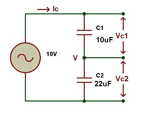
The two capacitors which are connected in series have the capacitance values of 10uF and 22uF respectively. Here the circuit voltage is 10V,this voltage is distributed between both capacitors.
In the series connection all the capacitors have same charge (Q) on it but the supply voltage (VS) is not same for all capacitors.
The circuit voltage is shared by the capacitors depending on the capacitance values of the capacitors.i.e. in the ratio of V = Q/C.
From these values we have to calculate the reactance (XC) of each capacitor by using frequency and capacitance values of capacitors.
Capacitive Voltage Divider Example No1
Now we will calculate the voltage distribution to the capacitors 10uF and 22uF which are given in the above figure which have 10V supply voltage with 40HZ frequency.
Reactance of 10uF capacitor,
XC1 = 1/2πfC1 = 1/(2*3.142*40*10*10-6) = 400Ω
Reactance of 22uF capacitor,
XC\2 = 1/2πfC2 = 1/(2*3.142*40*22*10-6) = 180Ω
Total capacitive reactance of a circuit is,
XC= XC1+ XC2= 400Ω + 180Ω = 580Ω
CT= C1C2/(C1+C2) = (10*22*10-12)/(32*10-6) = 6.88uF
XCT = 1/2πfCT = 1/(2*3.142*40*6.88*10-6) = 580Ω
The current in the circuit is,
I = V/XC = 10V/580Ω = 17.2mA
Now, the voltage drop across each capacitor is,
VC1 = I*XC1 = 17.2mA*400Ω = 6.9V
VC2 = I*XC2 =17.2mA*180Ω = 3.1V
Capacitive Voltage Divider Example No2
Now we calculate the voltage drops across the capacitors 10uF and 22uF which are connected in series and they operate with 10V supply voltage of 4000HZ (4KHZ) frequency.
Reactance of 10uF capacitor,
XC1 = 1/2πfC1 = 1/(2*3.142*4000*10*10-6) = 4Ω
Reactance of 22uF capacitor,
XC\2 = 1/2πfC2 = 1/(2*3.142*4000*22*10-6) = 1.8Ω
Total capacitive reactance of a circuit is,
XC= XC1+ XC2 = 4Ω+1.8Ω = 5.8Ω
CT = C1C2/(C1+C2) = (10*22*10-12)/(32*10-6) = 6.88uF
XCT = 1/2πfCT = 1/(2*3.142*4000*6.88*10-6) = 5.8Ω
The current in the circuit is,
I = V/XCT = 10V/5.8Ω = 1.72A
Now, the voltage drop across each capacitor is,
VC1 = I*XC1 = 1.72A*4Ω = 6.9V
VC2 = I*XC2 = 1.72A*1.8Ω = 3.1V
From the above two examples we can conclude that the lower value capacitor (10uF) will charge to a higher voltage (6.9V), and the higher value capacitor (22uF) will charge itself to a lower voltage level(3.1V).
Finally the sum of two capacitor voltage drops values are equal to the supply voltage (i.e. 6.9V+3.1V=10V). These voltage values are same for all frequency values, because the voltage drop is independent of frequency.
The voltage drops for the two capacitors is same in both the examples where the frequency is different. The frequency is either 40HZ or 40KHZ the voltage drops across capacitors is same in both cases.
The current flowing through the circuit changes depending on the frequency. Current will increase with increasing the frequency, it is 17.2mA for 40HZ frequency but it is 1.72A for the frequency 4KHZ, i.e. the current will increase almost 100 times by increasing frequency 4HZ to 4KHZ.
Finally we can say that the current flowing through the circuit is directly proportional to the frequency (I α f).
Summary
- The opposition for the flow of current in the capacitor is known as reactance (XC) of a capacitor. This capacitive reactance is influenced by the parameters like capacitance value,frequency of supply voltage and also these values are inversely proportional to the reactance.
- The AC voltage divider circuit will distribute the supply voltage to all the capacitors depending on their capacitance value.
- These voltage drops for the capacitors are same for any frequency of supply voltage. i.e. the voltage drops across capacitors are independent on frequency.
- But the current flowing is depending on frequency and also these two are directly proportional to each other.
- But in DC voltage divider circuits, it is not an easy task to calculate the voltage drops across capacitors as it depends on reactance value, because the capacitors block DC current flow through it after fully charged.
- The capacitive voltage divider circuits are used in large electronics applications.Mainly used in capacitive sensitive screens those change their output voltage when it is touched by a person finger.
- And also used in transformers to increase voltage drop where generally the mains transformer contains low voltage drop chips and components.
- Finally one thing to say is in voltage divider circuit the voltage drops across capacitors are same for all frequency values.

One Response
Good work. Very much informative. Thank you