In this tutorial, we will learn about Autotransformers. This is a complete guide to theory and design of Autotransformer, its efficiency numbers, electrical symbols, starting technique, protection measures, advantages, disadvantages, applications and many more.
Introduction
The Transformers are electromagnetic devices that transfer electrical energy from one circuit to another by principle of mutual induction. Mutual induction is the coupling of inductances by their mutual magnetic fields. For example in a single-phase transformer there are two coils, a primary and a secondary coil.
The primary coil will get the power from any electrical source like an AC generator. The magnetic field produced by the primary induces a voltage into the secondary coil. This secondary coil will be connected to the load and gets the supply accordingly.
Transformers are used to increase the voltage up to a higher level and they are called step up transformers. In the same way the transformers decreases the voltage down to a lower level and they are called as Step down transformers.
What is an Autotransformer?
As stated above a normal transformer will have two windings which are physically separated but magnetically coupled together with the help of a magnetic core. As they are separately been isolated, they are called as primary winding which receives the voltage from the source and secondary winding which transfers to the output load.
But the transformer in which there will be only one winding which is common to both primary and secondary is called Autotransformer. The term Auto here refers to that the voltage input variations will be automatically can be improved or can be reduced utilizing the single winding.
Auto Transformers are used in applications where there is no requirement for electrical insulation between input and output windings. These are popular for industrial automation and marine applications.
Autotransformer Theory and Design

In the autotransformer, part of the energy is transferred by induction and the rest is by conduction. There are three types of auto transformers: step-up, step-down, and variable auto transformers which can be either step-up or step-down the voltage.
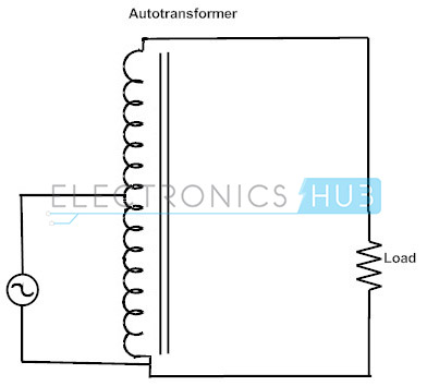
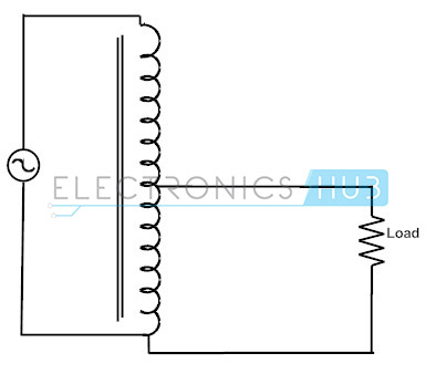
Variable auto transformers are used in the laboratory and industry to provide a wide range of ac voltages from a single source. The above figures show step-up and step-down autotransformers.
In the above Figures, the first winding is shown connected in an additive manner to the secondary winding. Now, the relationship between the voltage on the first winding and the voltage on the second winding is given by the turn’s ratio of the transformer.
However, the voltage at the output of the whole transformer is the sum of the voltage on the first winding and the voltage on the second winding. The first winding here is called the common winding, because its voltage appears on both sides of the transformer. The small winding is called the series winding, because it is connected in series with the common winding.
The voltage relationship in an autotransformer as shown in the above Figure (a) is given by
V₂= Vc + Vse
But,
Vc / Vse = Nc / Nse
===> V₂ = Vc + (Nc /Nse) * Vc;
But,
V₁ = Vc
===> V₂ = V₁ + (Nc /Nse) * V1 = ((Nc +Nse)/ Nse) * V₁;
The current relationship between two sides in an autotransformer as shown in above Figure (a) is given by
I₁ =Ic + Ise
But,
Ic = (Nse/Nc) * Ise
===> I₁ = Ise + (Nse/Nc) * Ise
But,
I₂ = Ise
===> I₁ = I₂ * (1 + (Nse/Nc))
It is interesting to note that not all the power travelling from the primary to the secondary in the autotransformer goes through the windings. As a result, if a conventional transformer is reconnected as an autotransformer, it can handle much more power than it is originally rated for. Notice that the input apparent power to the autotransformer is given by
Sin = V₁I₁;
and the output apparent power is given by,
Sout = V₂I₂.
It is easy to show that the input apparent power is equal the to the output apparent power so that
Sin = Sout =SIO
Here SIO is defined as the input and output apparent power of the transformer. The relationship between the power going into the primary of the transformer and actual windings can be found by
Sw =VcIc = VSE * ISE
Sw =V₁ * (I₁-I₂)
Sw =V₁I₁ – V₁ I₂
For the better understanding purpose let us consider an example.
An autotransformer of 500 Kva rating connecting 110 Kv line to 138 Kv line so Nc/Nse ratio will be 110/28. Now using the about derived formula of winding power and apparent power, we can calculate the actual power being travelled through the windings.
Sw = Sio x Nse / (Nse + Nc)
Sw = (5000) x 28/ (28+110) = 1015 KVA
It means actual winding power handling capacity is only 1015 KVA but this autotransformer can handle 5000 KVA means auto transformer can handle 5 times more power and 5 times smaller than a conventional 2 winding transformer.
It means we have to design and select copper wire for only handling power up to 1015kva. If we have operating voltage 220 then apparent current will be
Apparent Current = 1015 Kva/220 = 1015 x 1000/220= 4613.63 A.
We can select copper wire from SWG or AWG wire gauge table for proper current density.
The Auto transformer can also be constructed with more than one single tapping point. Auto-transformers can be used to provide different voltage points along its winding.
Auto transformer with Multiple Tapping Points
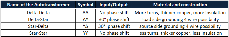
The following table will explain the different types of auto transformers according to their connection:
Autotransformer Symbols
1-Phase Autotransformer symbol
3-Phase Autotransformer symbol
Types of Autotransformers
There are 3 general types of auto transformers categorised on the basis of the use of autotransformer:
- Step Up Auto transformer
- Step Down Auto transformer
- Variable Auto transformer
Step Up Auto transformer
In this type of autotransformer input voltage is stepped up to the desired voltage and output voltage will depend on the turn ratio of the auto transformer.
This is the connection diagram of Step-up auto transformer:
As we have already discussed consider each loop of inductor as a battery more loops in the output circuit mean more ac voltage compared to the input. We know that the input and output apparent power is same so if we are going to step-up the voltage then definitely current will be decreased in order to maintain the power balance.
Step Down Auto transformer
Construction is same for both step up and step down autotransformer but in this configuration primary voltage is high and secondary voltage is low that’s why it is called step down transformer.
Variable Auto transformer ( Variac or Dimmer Set)
Fixed turn ratio auto transformers are widely used for many applications but sometimes it is required to have variable output voltage capability. Such transformers are very useful because they can be adjusted to any required voltage by just rotating the knob. They can be used in the place of step up and step down auto transformer.
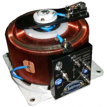
The center part of this round inductor is the knob. The voltage varies by rotating the knob of the autotransformer. Variable autotransformer can be equipped with many taps as required by the particular application and act as Ac voltage regulator.
By addition of some sensing circuitry these variable auto transformer can be used as automatic voltage regulator. This is also known as variac or dimmer set.
Starting of Autotransformer
When transformers are connected across the power line the starting current of the connected equipment will be 10 to 15 times more than the rated current of the equipment, then the total current flows through the 2 windings of the transformer for a fraction of time.
In some steroidal transformers inrush current is 60 times more than its rated capacity. In large transformers this transient current can stay for a couple of seconds until the equilibrium or settling time is being achieved.
In the same way in the autotransformer Inrush current also severe when the power supply is connected to transformer at an instant when the voltage is crossing the zero transit time where the load current depends on the resistance and inductance of the windings of the transformer.
For large transformers with very high inductances compared to the load transient current time will also be large and vice versa.
Auto transformer Efficiency
Auto transformer efficiency is much high as compared to the 2 winding transformers. Auto transformers efficiency sometimes reaches 99% with all comfortable conditions.
Efficiency = (Pout / Pin) * 100
Pout= Vs * Is * Cos(Ø)
Power Factor= Cos(Ø)
Pin= Pout +Ploss
Losses: In any kind of transformer there are mainly 2 types of losses
- Copper loss
- Core loss
Copper loss can be calculated by the short circuit test and iron or core loss is calculated by the open circuit test. Once both losses are calculated algebraic sum of both of these losses is the total loss in the autotransformer.
Auto transformer Impedance Calculation
Auto transformers have one addition disadvantage as compared to 2 winding transformers. It turns out to be for a given autotransformer the per unit impedance is less as compared to the 2 winding conventional transformer by the factor equal to the power advantage of the auto transformer over conventional one.
This less internal impedance can be a serious problem in such cases where reducing the current in power system faults like short circuit so in this situation, it is highly desirable to limit the current to reduce the chance of more damage.
Now let us calculate the internal impedance of the autotransformer.
Auto transformer Impedance Example
Conventional transformer of 1000kva voltage ration 12/1.2 Kv, 60Hz now this transformer is to be used as 13.2/12 Kv autotransformer in power system now calculate the power advantage of this auto transformer and calculate the auto transformers series impedance per unit.
2 winding transformer impedance is given= 0.01 + j0.08.
Sol:
Turn ration: Nc/Nse = 12/1.2 =10
Sio= (Nse + Nc/Nse ) * Sw
Sio = (1+10/1) x 1000 = 11,000Kva
So power advantage factor is 11.
As we know the 2 winding transformer impedance is Zeq = 0.01 + j0.08
So the autotransformer impedance will be Zeq = (0.01+j0.08)/11 = 0.00091+ j0.00727
We can see the internal impedance of autotransformer is 11 times less than the conventional 2 winding transformer.
Auto Transformer Earthling or Grounding
It is also known as grounding auto transformers. It is mainly used to generate the neutral wire in 3 phase 3 wire ungrounded system. It is connected in the form of zigzag or T-connected transformers. These transformers have continues of phase and neutral current rating.
Auto transformer Example
An 11,500/2300 V transformer is rated at 150 kVA as a two-winding transformer. If two windings are connected in series to form an autotransformer, what will be the voltage ration and the output?
The two windings of a two-winding transformer can be connected in series to form an autotransformer. In two windings either of winding is used as a secondary. Therefore the voltage ratio and the output of the transformer will depend on the winding which is used as a secondary winding.
Case-1:
The 2300 winding is used as the secondary.
The rating of the two-winding transformer St = 150kVA
Primary voltage of the autotransformer, V1 = 11500+2300 = 13.8 kV
Secondary voltage of the autotransformer, V2 = 2.3 kV
The two winding transformer voltage ratio a = V1/V2 = N1/N2 = 11.5 / 2.3 = 5
The autotransformer voltage ratio a’ = V1/V2 = (V1 – V2 + V2)/ V2 =a + 1 = 6
The turns ratio a = 13.8/2.3 = 6
Rating of the transformer St = (V1 –V2) * I1 = (I2 –I1) * V2
Rating of the auto transformer = Sat = V1 * I1 = V2 * I2
But (I2-I1) / I1 = N1/N2 = a
Then I1 = (1/(1+a))I2
Therefore St = V2 ((V1/V2) – 1) (1/ (1+a)) * I2 = (a / (1+a)) Sat
Therefore Sat = ((1+a)/a) x 150 = 180kVA.
Case 2:
The 1150 V winding used as the secondary.
V1 = 13.8 kV
V2 = 11.5 kV
Voltage ratio = a’ = 13.8/11.5 = 1.2
Voltage ratio = a = (13.8 – 11.5) / 11.5 = 0.2
Now Sat = ((1+a) / a) x 150 = 900 kVA
3-Phase Autotransformer
A three phase auto transformer is special type in which common winding is being shared by the high voltage and low voltage. Three phase AC being supplied at primary and output is collected at secondary. Three phase auto transformer is used for such application where small voltage is used in distribution system. There is no electrical isolation is provided between them. It is designed for step up and step down voltage and work on magnetic induction principle.
The key features of three phase auto transformer are as follows:
- 3 KVA to 500 KVA rating
- 50/60 Hz frequency
- Three phase
Three phase auto transformer is used in power application to connect system operating at voltage level ranging from 66Kv to 138Kv transmission line.
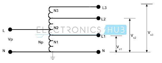
The general 3 phase autotransformer will be as per the following diagram:

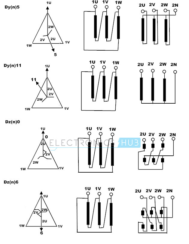
Below is another type of connection and its Vector diagram:
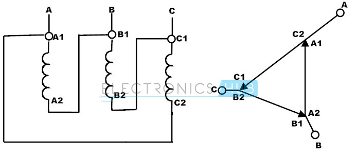
The following diagram explains different types of 3 phase autotransformer connections.
3-Phase Autotransformer Rating
It is rated in KVA ranging its capacity from (1 KVA-500KVA). Its tolerance range (±5%). The insulating resistance being used in 3 phase auto transformer is 2000MΩ.
To calculate the three phase KVA we use below formula
KVA = (volts*amp*1.73)/1000
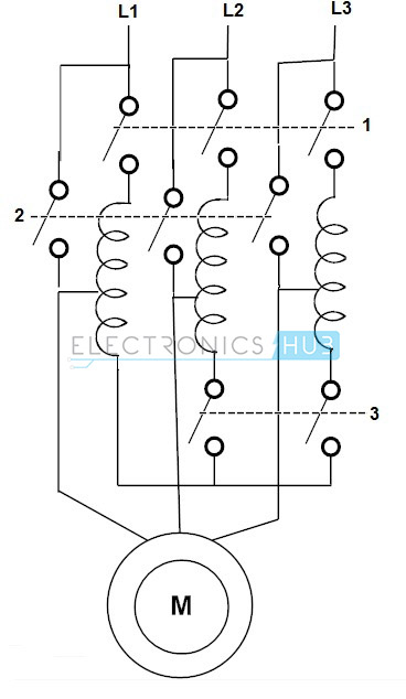
Autotransformer Starter of Induction Motor
The principle of auto transformer is similar to star delta starter method. The starting current is limited by using 3 phase auto transformer. Auto transformer can be replaced with the star delta starters and with other starters which are more expensive and being complicated in operation. Auto transformer is suitable for both star and delta connected motor, starting current and torque can be adjusted by taking correct tapping from auto transformer. It gives highest motor torque per line ampere.
Additional Information on Autotransformers
Autotransformer Features
Ratings of autotransformer starters are less than the conventional motor starter ratings for the higher kilowatt motors. Main, size of auto transformer is very small, so effective material will reduce the cost. Effectively reducing the material makes the copper and iron losses less so auto transformer when compared to normal isolation transformers, have high efficiency.
Auto transformer Protection
Normal transformer Differential protection relays and accessories can be used for Auto transformer protection also. Transformer differential protection contains a number of additional functions (matching to transformation ratio and vector group, stabilisation (restraint) against inrush currents and over excitation) and therefore requires some fundamental consideration for configuration and selection of the setting values.
The additional functions integrated per relay can be used to advantage. However, it must be considered that backup protection functions must be arranged in separate hardware (further relay) for reasons of hardware redundancy.
This means that the over current-time protection in the differential protection can only be used as backup protection against external faults in the connected power system. The backup protection for the transformer itself must be provided as a separate over current relay. The Buchholz protection as fast short-circuit protection.
Different types of auto-transformer differential protection schemes have been presented. Which scheme will be used is mostly determined by the availability of the main CTs in a particular installation.
It is recommended that in addition to the standard differential protection scheme additional differential scheme is applied, which is sensitive to the faults close to the common winding star point. Another possible solution is to combine two different schemes which have different properties.
Due to the size and importance of auto-transformers in modern power systems (e.g. mostly used as system intertie transformers) full duplication of the protection scheme is typically easily justified.
Autotransformer Tertiary Winding Protection
From the differential relay point of view, the differential protection scheme is same for normal isolation transformers and to the autotransformers. The only difference is that all three individual currents within tertiary delta winding are available to the relay.
Consequently the tertiary delta winding can be loaded with such arrangement. Used equation and advantages of such differential scheme can be easily calculated and can be implemented. In auto transformer tertiary delta winding is used.
It is used to limit the generation of harmonics voltages which are caused by magnetizing currents affecting the lower zero sequence impedance. The tertiary delta winding is one third rated through power of auto transformer. It redistributes the flow of current detected from fault. It also reduces the unbalancing being used in three phase load.
Autotransformer Testing Procedure
When transformers are received from the factory or relocated from another location it is necessary to verify that each transformer is dry, no damage has occurred during shipping, internal connections have not been loosened, the transformer ratio, polarity, and impedance agree with its nameplate, its major insulation structure is intact, wiring insulation has not been bridged, and the transformer is ready for service.
Physical size, voltage class, and kVA rating are the major factors that dictate the amount of preparation required to put transformers in service. Size and kVA rating also dictate the kind and number of auxiliary devices a transformer will require.
All of these factors affect the amount of testing necessary to certify that a transformer is ready to be energized and placed in service.
Some tests and procedures may be performed by specialists during the assembly phase. Special tests, other than the listed, may also be required. Many require special equipment and expertise that construction electricians do not have and are not expected to provide.
Some tests are performed by an assembly crew, while other tests are done by the person(s) making the final electrical tests on the transformers.
Also, the following test descriptions provide an anchor point from which to ask for help when needed. The following items are discussed or described:
- Nameplate Data
- Power Meggering
- Auxiliary Components and Wire Checks
- Lightning Arrestors
- Hand Meggering
- Temperature Devices
- CT Tests
- Winding Temperature and Thermal Image
- Bushing Power Factoring
- Remote Temperature Indication
- Transformer Power Factoring
- Auxiliary Power
- Voltage Ratio
- Automatic Transfer Switch
- Polarity
- Cooling System
- Transformer-Turns Ratio
- Bushing Potential Device
- Tap Changers
- Auxiliary-Equipment Protection and Alarms
- Short-Circuit Impedance
- Overall Loading
- Zero Sequence
- Trip Checks
- Winding Resistance
Following is an approximate sequence for transformer testing:
- Inspect transformer and parts for shipping damage and moisture.
- Check nameplate and prints for proper voltages and external phasing connection to the line or bus.
- Check calibration of all thermal gauges and hot-spot heater, bridge RTDs and associated alarm contacts. Contact settings should be similar to the following.
- One stage runs all the time (forced cooling)
- 2nd stage at 80°C
- 3rd stage at 90°C
- Hot-spot alarm 100°C (trip at 110°C when applicable)
- Top-oil alarm 80°C at 55°C rise and 75°C at 65°C rise
- OA = no fans or pumps
- FA =fans running
- FOA = fans and pumps running
- Check and Megger all wiring point to point: Fans, pumps, alarms, heaters, tap changers, and all other devices on the transformer and interconnecting cables.
- All banks above 150 MVA should be vacuum dried. Do not apply test voltages to the winding during the vacuum drying process. Make certain the terminals are shorted and grounded during oil circulation because of the large amount of static charge that can build up on the winding.
- After the tank has been filled with oil, confirm that an oil sample was sent to the Chemical Lab and that its results are entered in the bank test reports. Note the oil level and temperature at completion of filling.
- Power operate to verify proper rotation of pumps and fans and correct operation of the under load (UL) tap changer, when provided. Also, check heater, alarms and all other devices for proper operation.
- Following are the winding tests to be performed:
- Impedance
- DC winding resistance
- Megger and Power Factor windings, bushing and arrestors.
- Note: Wait until 24 hours after completion of oil filling for Power Factor testing.
- Load CT circuits overall and flash for polarity.
- Before energization, trip-check bank protection schemes and make sure the gas collection relay is free of gas.
- When energizing a bank or picking up load, monitor bank currents and voltages, including UL tap-changer operation.
- Check proper phasing and voltage of the bank to the system before load is picked up. When possible, large transformers (>1 MVA) should remain energized for eight hours before carrying load.
- Make in-service checks on meters and relays.
- Release to Operations and report energization information to the TNE office.
- Turn in revised prints and test reports, which should include the following:
- All test data
- Moisture and oil data
- Problems incurred
- In-service data
- Time energized and release to operation
Advantages of Autotransformer
- Losses are decreased for given KVA capacity.
- Saving in size and weight.
- Size is very smaller.
- Voltage regulation is much better.
- Cost is low.
- Excitation current requirement is low.
- For designing auto transformer copper is used in less requirement.
- In conventional transformer step up and step down voltage are fixed while in auto transformer output vary as per the requirement
Disadvantages of Autotransformer
- Higher levels of protection to the equipment and for human beings are required because of higher short circuit currents and because of low series impedance of the autotransformer which damages both equipment as well as threat to human-beings.
- If any winding of auto transformer short circuited the output voltages will swing to higher voltages than operating voltage causing a very huge damage.
- It consists of single winding around the iron core which develops change in voltage from one end to the other. There is no isolation of low and high voltages either at the input or at the output of the transformer. So any noise or voltage pertaining on one side will reflects on the other side. So Filtering circuits are necessary wherever auto transformer is used in electronic circuits.
Autotransformer Applications
- It is used in synchronous and induction motors as a part of starting purpose.
- It is used in electrical apparatus testing labs
- It is used as boosters in AC feeders to increase the desired voltage level.
- Used for starting of squirrel cage motors and slip-ring induction motors.
- For interconnecting systems that are operating in threshold voltages.
- As boosters to rise the incoming voltages
Limitations of Autotransformer
- Cannot be used for isolated operable systems as the earth or ground is common for both input and output connected equipment.
- Safety concern issues stringently to be taken, as the common ground phenomenon may create a human threat.
- A failure of the winding insulation of the autotransformer will result in full input voltage applied to the output.
Summary
- Autotransformers are transformers in which the primary and secondary windings are coupled magnetically and electrically.
- This results in lower cost, and smaller size and weight.

4 Responses
Very very well
Rally I am in doubt to connect a three phase autotransformer in Delta/star with neutral bolted to ground and it implications in term of multiple grounding situation
Hi sir in variable auto transformer for 8amps current drawing wire swg is 19 swg how its pls send me with examples
Thanking you sir
B. T Reddy
Thank you for the data