Automatic Door Opening System is a simple automated system, where the door is automatically opened up on detecting a person and automatically closes after some time.
Opening and closing of doors have been always a tedious and boring job, especially in places where a person is always required to open the door for visitors such as hotels, shopping malls, theaters, etc.
Automatic door opening systems are used in many places like shopping malls, bur or railway stations, airports, etc. to eliminate manual control of opening and closing the doors.
Automatic door opening systems can be implemented using different sensors like Infrared, pressure, ultrasonic, laser etc. This project deals with an interesting manner of automating the process of opening and closing the door by detecting the presence of a human.
Principle of Automatic Door Opening System
The principle of the project lies in the functioning of the PIR Sensor. A PIR or Passive Infra-red Sensor, as the name indicates, doesn’t emit infrared rays but only detects them.
All humans emit infrared radiations in the form of body heat. A PIR Sensor will capture the difference between the room temperature and body temperature in the form of change in infrared radiation.
This change in infrared pattern is converted to a voltage. The voltage from the Data Out of the PIR Sensor can be given to a microcontroller for further processing like controlling a motor etc.
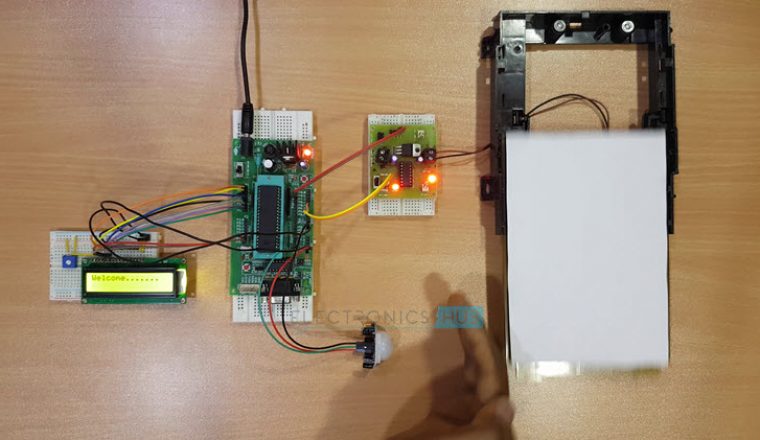
Circuit of Automatic Door Opening System

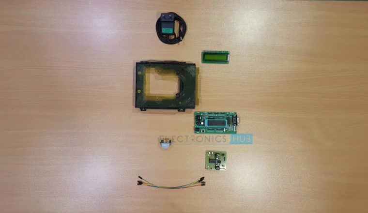
Components
- AT89C51 Microcontroller
- AT89C51 Programmer Board
- 11.0592 MHz Quartz Crystal
- 2 x 22pF Ceramic Capacitor
- 2 x 10KΩ Resistor
- 10µF Electrolytic Capacitor
- Push Button
- 16 x 2 LCD Display
- 3 x 1KΩ Resistor
- 10KΩ POT
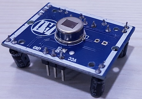
- Passive Infrared Sensor (PIR Sensor)
- L293D Motor Driver
- Motor
- Connecting Wires
Component Description
PIR Sensor
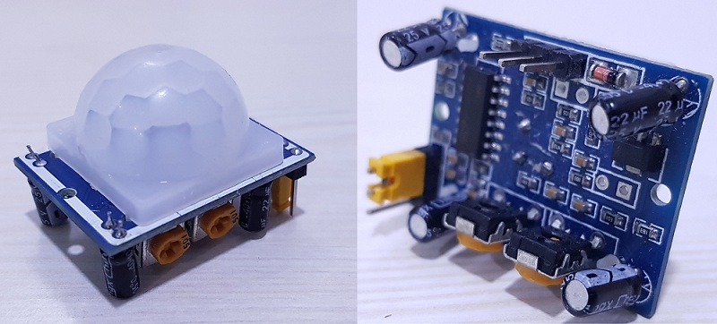
- PIR( Passive Infra-Red) Sensor is a pyroelectric device.
- Generally, a human body emits heat in the form of infrared energy. A PIR sensor detects the motion by checking for the sudden changes in the surrounding infrared pattern.
- The PIR sensor has a 3-pin connection.
- Pin 1 is the Vcc pin. It must be connected to 5V supply.
- Pin 2 is the Data Out pin.
- Pin 3 is the Ground pin. It must be connected to ground.
- The range of this sensor is 30 feet. It can be reduced to 15 feet using a jumper.
The output of a PIR sensor is a digital output. So interfacing a PIR with microcontroller is very easy and simple as all you need to do is to check for the pin to go high or low.
For proper operation, the PIR sensor must be given a warm up time of 20 to 60 seconds. During this time, the PIR sensor calibrates itself .If the sensor is not given enough calibrating time, the output of the PIR sensor may be erroneous.
L293D Motor Driver
The motor driver used in the project is L293D. It is a dual H-bridge motor driver integrated circuit (IC).
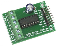
Motor drivers act as current amplifiers since they take a low current control signal and provide a higher current signal which drives the motors.
It can drive two motors simultaneously in its common mode, both in forward and reverse direction. L293D Motor Drive is available in 16-pin Dual in-line Package.
How to Design Circuit of Automatic Door Opening System?
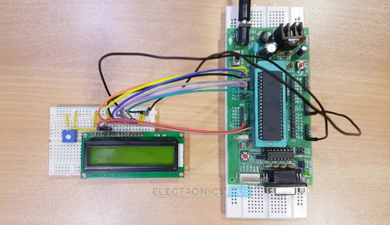
The main components of the project are 8051 Microcontroller, 16 x 2 LCD Display, PIR Sensor, L293D Motor Driver and a motor.
First we’ll see the connections of microcontroller. A reset switch is needed to reset the microcontroller. The reset switch is generally associated with a 10K Resistor and a 10uF capacitor. The connections are mentioned in the circuit diagram.
An 11.0592 MHz crystal along with two 22pF Capacitors will form the external oscillator circuit for the microcontroller. The EA pin must be connected to Vcc using a 10K Resistor.
The 16 x 2 LCD is used to display the status and other messages. The connections of the LCD are mentioned in the circuit diagram. A 10K POT is connected to Pin 3 of the LCD to adjust the contrast.
The RS, RW and E pins of the LCD must be connected to PORT 0 pins i.e. P0.0 to P0.2. But before that, the PORT 0 pins must be pulled high using 1K resistors. The data pins of the LCD i.e. D0 to D7 are connected to PORT 2 of the microcontroller.
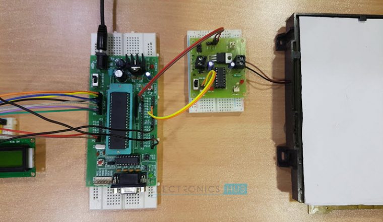
The PIR Sensor has only one data out pin. It must be connected to P3.0 of the microcontroller. The other two pins are power supply pins.
The next component is the motor driver. Connect the two input pins i.e. IN1 and IN2 (Pins 2 and 7) to P3.6 and P3.7 of the microcontroller. Also the Enable 1 (EN1 – Pin1) is connected to Vcc to enable the driver channel 1. A motor is connected to OUT1 and OUT2 (Pins 3 and 6) of the motor driver.
Step-by-step guide with CODE: Automatic Door Opener System using 8051
How Automatic Door Opening System Works?
The aim of this project is to design an Automatic Door Opening system using 8051 microcontroller, in which the door is automatically opened and closed by detecting the movement of a person.
Before going to the working of the project, let us see the basic requirements of the project.
- When a person approaches the door through the doorway, the system must detect the person and open the door automatically.
- The door should stay open as long as the doorway is not clear i.e. as long as the system detects a person.
- Once the doorway is cleared, the system must close the door automatically and wait for the next person.
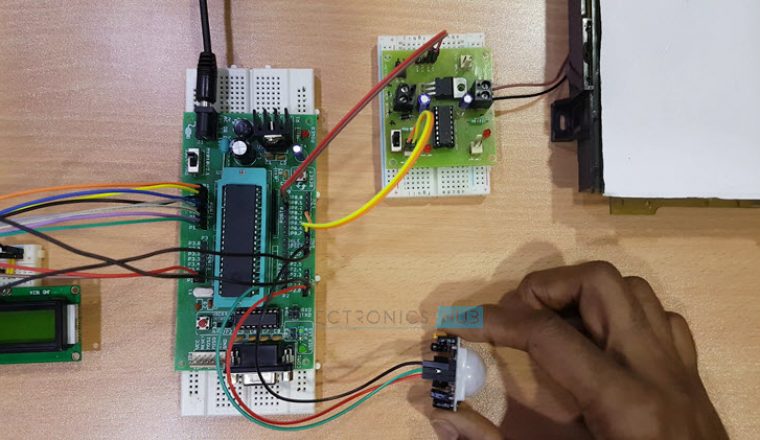
Considering the above requirements, the working of the project is explained here. Once we turn on the circuit, the microcontroller will initialise the PIR sensor with a settling time of 20 seconds for the sensor to calibrate the surroundings. During this time, the LCD will display the message as Loading.
Once the setup is done, the PIR sensor is now ready to detect the human movement within its range. At this time, the microcontroller will display the message as Scanning on the LCD display.
If there is any human movement in front of the PIR Sensor, it will detect the movement and indicate the microcontroller by making the data out pin Logic HIGH.
Now, the microcontroller will open the door by initialising the motor driver. A welcome message is displayed on the LCD. The door remains open as long as the data out from the PIR Sensor is high.
When there is no human movement, the data out of the PIR Sensor becomes LOW. Once the data out is LOW, after a small delay, the door is automatically closed and comes back to initial position.
Applications and Advantages
- Automatic Door Opening System can be implemented where the door is automatically opened and closed without any manual control.
- Since the door is opened only when a person is detected and remains close all other times, it can save a lot of energy in the form air conditioning.
- An automatic door system with sliding doors can be useful for aged and disabled.
- Can be implemented with additional features like face detection to track the trajectory in security applications.

5 Responses
hi anusha i like to do this project can u help me
nice
Hello
Can i get a YouTube video for how to make this project .
no u cant
actually I really appreciate because is interesting. thank you so much.