Counters remember the digital combinations of data. Counters are used everywhere and every time in our day to day life. Example is the digital clock alarm that wakes you up in the early morning.
There are two types of counters
- 1) Synchronous and
- 2) Asynchronous.
Asynchronous Counters
Asynchronous counters are those whose output is free from the clock signal. Because the flip flops in asynchronous counters are supplied with different clock signals, there may be delay in producing output.
The required number of logic gates to design asynchronous counters is very less. So they are simple in design. Another name for Asynchronous counters is “Ripple counters”.
The number of flip flops used in a ripple counter is depends up on the number of states of counter (ex: Mod 4, Mod 2 etc). The number of output states of counter is called “Modulus” or “MOD” of the counter. The maximum number of states that a counter can have is 2n where n represents the number of flip flops used in counter.
For example, if we have 2 flip flops, the maximum number of outputs of the counter is 4 i.e. 22. So it is called as “MOD-4 counter” or “Modulus 4 counter”.
Different types of Asynchronous counters
There are many types of Asynchronous counters available in digital electronics. They are
- 4 bit synchronous UP counter
- 4 bit synchronous DOWN counter
- 4 bit synchronous UP / DOWN counter
Asynchronous 4-bit UP counter
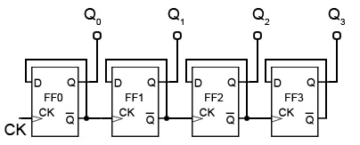
A 4 bit asynchronous UP counter with D flip flop is shown in above diagram. It is capable of counting numbers from 0 to 15. The clock inputs of all flip flops are cascaded and the D input (DATA input) of each flip flop is connected to a state output of the flip flop.
That means the flip flops will toggle at each active edge or positive edge of the clock signal. The clock input is connected to first flip flop. The other flip flops in counter receive the clock signal input from Q’ output of previous flip flop. The output of the first flip flop will change, when the positive edge on clock signal occurs.
In the asynchronous 4- bit up counter, the flip flops are connected in toggle mode, so when the when the clock input is connected to first flip flop FF0, then its output after one clock pulse will become 20.
The rising edge of the Q output of each flip flop triggers the clock input of its next flip flop. It triggers the next clock frequency to half of its applied input. The Q outputs of every individual flip flop (Q0, Q1, Q2, Q3) represents the count of the 4 bit UP counter such as 20 (1) to 23 (8).
Working of asynchronous up counter is explained below,
Let us assume that the 4 Q outputs of the flip flops are initially 0000. When the rising edge of the clock pulse is applied to the FF0, then the output Q0 will change to logic 1 and the next clock pulse will change the Q0 output to logic 0. This means the output state of the clock pulse toggles (changes from 0 to1) for one cycle.
As the Q’ of FF0 is connected to the clock input of FF1, then the clock input of second flip flop will become 1. This makes the output of FF1 to be high (i.e. Q1 = 1), which indicates the value 20. In this way the next clock pulse will make the Q0 to become high again.
So now both Q0 and Q1 are high, this results in making the 4 bit output 11002. Now if we apply the fourth clock pulse, it will make the Q0 and Q1 to low state and toggles the FF2. So the output Q2 will become 0010¬2. As this circuit is 4 bit up counter, the output is sequence of binary values from 0, 1, 2, 3….15 i.e. 00002 to 11112 (0 to 1510).
For example, if the present count = 3, then the up counter will calculate the next count as 4.
Asynchronous 4-bit DOWN counter
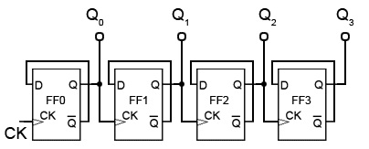
A 4 bit asynchronous DOWN counter is shown in above diagram. It is simple modification of the UP counter. 4 bit DOWN counter will count numbers from 15 to 0, downwards. The clock inputs of all flip flops are cascaded and the D input (DATA input) of each flip flop is connected to logic 1.
That means the flip flops will toggle at each active edge (positive edge) of the clock signal. The clock input is connected to first flip flop. The other flip flops in counter receive the clock signal input from Q output of previous flip flop, rather than Q’ output.
Here Q0, Q1, Q2, Q3 represents the count of the 4 bit down counter. The output of the first flip flop will change, when the positive edge of clock signal occurs. For example, if the present count = 3, then the up counter will calculate the next count as 2. The input clock will cause the change in output (count) of the next flip-flop.
The operation of down counter is exactly opposite to the up counter operation. Here every clock pulse at the input will reduce the count of the individual flip flop. So the down counter counts from 15, 14, 13…0 i.e. (0 to 1510) or 11112 to 00002.
Both up and down counters are designed using the asynchronous, based on clock signal, we don’t use them widely, because of their unreliability at high clock speeds.
What is clock ripple?
The sum of time delay of individual clock pulses, that drive the circuit is called “Clock ripple”. The below figure explains how the logic gates will create propagation delay, in each flip flop.
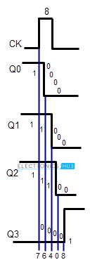 The propagation delays of logic gates are represented by blue lines. Each of them will add to the delay of next flip flop and the sum of all these individual flip flops is known as the propagation delay of circuit.
As the outputs of all flip-flops change at different time intervals and for every different inputs at clock signal, a new value occurs at output each time. For example, at clock pulse 8, the output should change from 11102 (710) to 00012 (810), in some time delay of 400 to 700 ns (Nano Seconds).
For clock pulses other than 8, the sequence will change.
Although this problem prevents the circuit being used as a reliable counter, it is still valuable as a simple and effective frequency divider, where a high frequency oscillator provides the input and each flip-flop in the chain divides the frequency by two. This is all about clock ripple.
Asynchronous 3-bit up/down counters
By adding up the ideas of UP counter and DOWN counters, we can design asynchronous up /down counter. The 3 bit asynchronous up/ down counter is shown below.
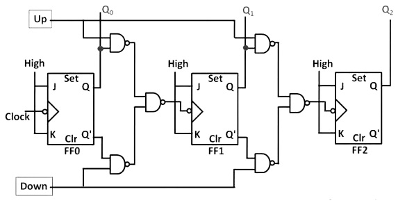
It can count in either ways, up to down or down to up, based on the clock signal input.
UP Counting
If the UP input and down inputs are 1 and 0 respectively, then the NAND gates between first flip flop to third flip flop will pass the non inverted output of FF 0 to the clock input of FF 1. Similarly, Q output of FF 1 will pass to the clock input of FF 2. Thus the UP /down counter performs up counting.
DOWN Counting
If the DOWN input and up inputs are 1 and 0 respectively, then the NAND gates between first flip flop to third flip flop will pass the inverted output of FF 0 to the clock input of FF 1. Similarly, Q output of FF 1 will pass to the clock input of FF 2. Thus the UP /down counter performs down counting.
The up/ down counter is slower than up counter or a down counter, because the addition propagation delay will added to the NAND gate network
Advantages
- Asynchronous counters can be easily designed by T flip flop or D flip flop.
- These are also called as Ripple counters, and are used in low speed circuits.
- They are used as Divide by- n counters, which divide the input by n, where n is an integer.
- Asynchronous counters are also used as Truncated counters. These can be used to design any mod number counters, i.e. even Mod (ex: mod 4) or odd Mod (ex: mod3).
Disadvantages
- Sometimes extra flip flop may be required for “Re synchronization”.
- To count the sequence of truncated counters (mod is not equal to 2n), we need additional feedback logic.
- While counting large number of bits, the propagation delay of asynchronous counters is very large.
- For high clock frequencies, counting errors may occur, due to propagation delay.
Applications of Asynchronous Counters
- Asynchronous counters are used as frequency dividers, as divide by N counters.
- These are used for low power applications and low noise emission.
- These are used in designing asynchronous decade counter.
- Also used in Ring counter and Johnson counter.
- Asynchronous counters are used in Mod N ripple counters. EX: Mod 3, Mod 4, Mod 8, Mod 14, Mod 10 etc.

5 Responses
thank you for the answer iam satisfied
If u could show for different types of flip flop using state diagram it would be nice and more understanding
figure shows in the asynchronous up and down counter should be clear.it is so difficult to understand and learn…..
Absolutely Correct.
Sir, Please guide for limitations of Ripple counters