Resistors are the basic components in almost all electrical or electronic circuits. Resistors control the amount of current that flow through them. They control the voltage in individual components connected to them. Without resistors, the individual components can’t handle the voltage and might result in overloading.
Applications of Resistors
Pull Up Resistors
In electronic circuits, it is essential that the input of a logic system is maintained or settled at a well-defined and a fixed logic value under all conditions. The logic circuits have three possible states viz. high, low and high impedance. High impedance state occurs when a pin is left floating i.e. not connected to either high or low. Hence it is also called as floating state.
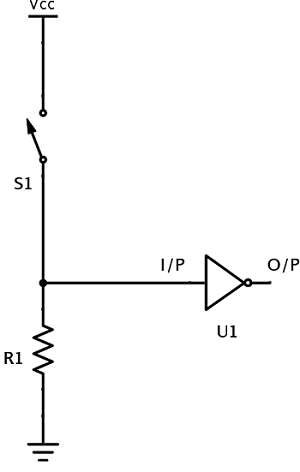
Consider the following circuit.
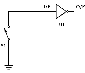
Here, the gate U1 which is an inverter has two pins – input pin and output pin.
When the switch S1 is closed, the input pin is connected to a definite electrical potential i.e. to ground in this case. Hence the state of input is low and the state is stable.
When the switch S1 is open, the input pin of U1 is in floating state i.e. not connected to any thing. In this case the input state of U1 is undetermined. This is a very weak state. Electrical noises in the circuit will cause wide array of problems. Due to these electrical noises, the input of the gate becomes high or low.
Hence a connection is needed to connect the input pin to electrical potential when the switch is open. This connection should be removed when the switch is closed. By following this technique we can keep the input pin of U1 at steady state when the switch is open or close.
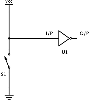
In the above circuit when the switch is open, the input is connected to VCC. This connection ensures that the input is connected to a valid electrical potential-VCC. Hence when the switch is open, the input is in HIGH state.
But there is a problem in the circuit when the switch is closed. When the switch is closed, there is a direct connection between VCC and ground. This direct connection will short the circuit. The least expected in this case is the entire system will cease to work. The worst case scenario is it will burn up the wires and the components connected to them.
The reason for this is the direct connection of VCC and ground will allow a large current to flow from VCC to ground. This connection generates great heat that might burn up wires and parts and may even start fire.
Hence it is essential to limit the amount of current that flows in the circuit.
A resistor is used in this scenario to avoid this problem. The function of this resistor is to limit the amount of current that flows in the circuit, when the switch S1 is closed. This resistor is named as Pull up resistor since it pulls the input to logic HIGH initially.
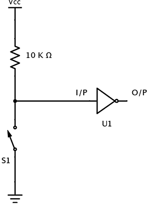
When the switch S1 is open, the input pin is connected to VCC through the resistor. This will make the state of the input pin as logic High.
When the switch is closed, the input pin of the gate is connected to ground. This will make the state of the input pin as logic Low.
A terminal of the resistor is connected to ground. Now the current will flow from VCC to ground through the resistor when the switch is closed. This connection is not considered as short because the resistor will reduce the amount of current to a significantly small value that is flowing from VCC to ground.
The amount of current flowing from VCC to ground when the switch is closed can be calculated using Ohm’s law.
If the supply voltage is VCC = 5V and the resistance of the resistor is 10 K Ω then I = VCC / R
I = 5 / (10 * 103)
I = 0.0005 Amps or I = 0.5 * 10-3 Amps
A pull up resistor is used in logic circuits to ensure that a pin is pulled to logic high in the absence of an input signal. Microcontrollers are used in embedded systems which are real time systems. Because of this the microcontrollers are sensitive to the smallest change in their inputs. Hence it is necessary to make sure that the input of a microcontroller will not be in a floating state.
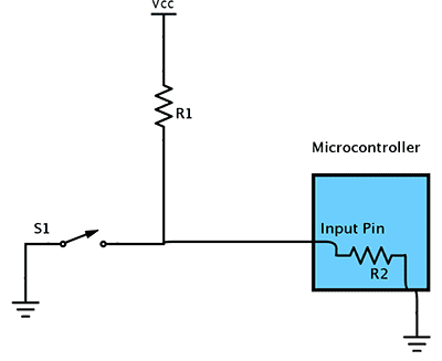
For example consider the following logic in a Microcontroller.
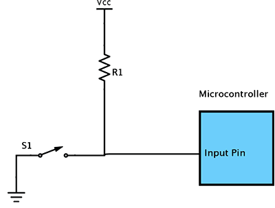
Here the resistor R1 acts as a pull up resistor. When the switch is not pressed or opened, the input pin of the Microcontroller will be at logic high. When the switch is closed, the input pin is pulled to logic low and small current flows from VCC to ground.
If the pull up resistor is absent then there is a direct connection between supply and ground which is considered as short circuit.
Selection of a correct pull up resistor is an important task. When the pull up resistor value is low, the condition is called Strong pull up. This is because more current flows through the input pin.
In contrast, when the pull up resistor value is high, the condition is called Weak pull up. This is because less current flows through the input pin.
There are two conditions that are needed to be satisfied while selecting a pull up resistor.
1. When the switch is closed, the input is connected to ground and is pulled to logic low. The value of the resistor R1 will decide the amount of current that flows from VCC to ground.
2. When the switch is open, the input pin of the microcontroller is pulled to logic high. The value of the resistor R1 will decide the voltage on input pin.
In general the resistance of pull of resistor should be ten times less than the resistance of microcontroller input pin
The resistance of the input pin of a microcontroller can be anywhere between 100 K Ω to 1 M Ω. Generally the value of the pull up resistor R1 is chosen in the region of 10 K Ω to 100 K Ω.
But when a large pull up resistor is chosen, the response of input pin is slow to the changes in voltage. This is because the input signal fed to the input pin will come from a system which is a capacitor coupled with pull up resistor. This combination forms an RC filter. This RC filter will take time to charge and discharge. This time can be calculated using the equation
τ (Tau) = R * C
If high data rates are required then the value of pull up resistor should be considerably less, generally it is in the order of 1 K Ω to 4.7 K Ω.
Practical values of pull up resistors are 10 K Ω and 4.7 K Ω.
Pull Down Resistors
The applications of pull down resistors are similar to pull up resistors except that it pulls the input pin to logic low initially.
When the switch S1 in the above circuit is closed, the input pin of the gate U1 is at a logic High state. When the switch is open, the resistor R1 pulls down the input pin voltage to ground.
For example, consider the following Microcontroller circuit.
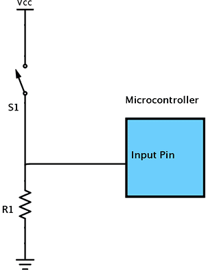
When the switch is pushed or closed, the input pin of microcontroller is at logic high value. If the switch is open then the pull down resistor pulls the input pin of the microcontroller to logic low.
Current Limiting Resistors
Current limiting is a process of setting an upper limit to the amount of current that flows through a component or a circuit. The purpose of limiting the current is to avoid effects like short circuit. Resistors can be used as current limiting devices.
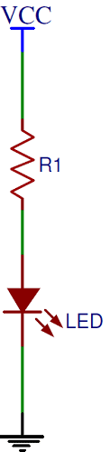
The best example is powering up a Light Emitting Diode (LED). An LED is a semiconductor device that emits light when a small current flows through it. The current in an LED is unidirectional just like a normal PN junction diode. The internal resistance of an LED is very low. When it is directly connected to a power supply, it will burn up.
Hence to power up an LED, a voltage source and a resistor are connected in series to LED. These resistors are called Ballast Resistors. LED’s are very sensitive to current. To light an LED few milli amperes of current is sufficient. All LED’s are designated with their current ratings. Hence we can choose an appropriate resistor that limits the current flow through the light emitting diode and prevents it from burning.
If the current rating of an LED is 0.15 amps then the value of the resistor for a supply of 5 V is calculated as follows (Assume Led rated voltage is negligible).
R = V / Iled = 5 / 0.15 = 333 Ω.
In some cases both voltage rating and current rating of the LED are specified. In such cases the appropriate resistance can be calculated using the below formula
R = (V – VLED) / ILED
where V is supply voltage, VLED is rated LED voltage and ILED is rated LED current
Transistor Biasing Resistors
Resistors are extensively used in electronic circuits in combination with Transistors and IC’s. Transistors (Bipolar Junction Transistors) require a small biasing voltage ≈ 0.7 V applied to the base terminal for them to work. When this biasing voltage is applied at the base terminal, a small current at base terminal causes a large current to flow from its collector terminal to its emitter terminal, which is the functionality of the transistor.
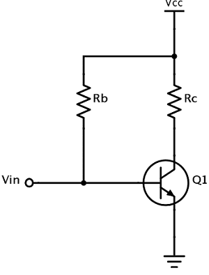
The base terminal of the transistor is vulnerable to high currents. Hence a resistor is used in the biasing circuit to limit the current that flows in to the base terminal of transistor.

One Response
Current always takes the low resistance path.
In pull down concept, current will choose to flow through the pull down resistor only. Because pull down resistor has lower value than micro controller’s pin resistance.
So micro controller will be in same state in both switch is open and switch is closed states.