This article is aimed to design and demonstrate a simple 5 channel remote control system to drive five loads. The input signals or the commands are sent from a transmitter using IR transmission and received by the IR receiver, processed and used to drive the loads. At both the transmitter and receiver, a microcontroller is used to process the signals.
Principle behind the Circuit:
The circuit works on the principle of IR communication. IR communication involves transmitting signals using infrared signal as the carrier. The input signal from switches is processed by the microcontroller, encoded by the encoder, modulated and transmitted by the transmitter. At the receiver, the modulated signal is demodulated by the IR receiver, decoded by the decoder and processed by the microcontroller to control the output loads.
Related Post: 8 Player Quiz Buzzer Circuit
5 Channel IR Remote Control Circuit Design:
The transmitter circuit consists of the three ICs – Atmel89C51 microcontroller, Encoder HT12E and timer 555.
The first step of the design includes designing the microcontroller interfacing. At the input side, a 5 item DIP switch is interfaced to port P1 of the microcontroller. Another part of the input circuit design involves designing the oscillator circuit and reset circuit. The oscillator circuit design is done by selecting two 15pF capacitors connected to both ends of the crystal oscillator.
The reset circuit is designed keeping in mind the required reset pulse width to be 100ms and voltage drop at reset pin to be 1.2V. Here we select a resistor of 10K and capacitor of 10uF to meet the requirements. The output side consists of the HT12E encoder with its 7 address pins and the terminal enable pin connected to ground, 4 data pins connected to Port 0.
The second step of the design involves designing the timer oscillator circuit. Here we need to be design a astable multivibrator using 555 timer. Keeping in mind the required oscillation frequency to be 38 KHz and assuming the value of capacitor to be 0.01uF, we get the value of Ra as 760 ohms and Rb as 1.5K.
The receiver circuit is similar to the transmitter circuit design and consists of four ICs- Atmel89C51, decoder HT12D, IR receiver TSOP1738 and relay driver ULN2004. Designing the microcontroller interfacing is same as that in the transmitter circuit, specially the reset circuit and oscillator design.
Here, the input circuit consists of the decoder and TSOP1738. The output pin of TSOP 1738 is connected to data input pin of the decoder IC and the 4 data output pins are connected to port P1 of the microcontroller. The address pins are grounded and an LED is connected to the valid transmission pin to indicate the transmission.
The output circuit consists of the relay driver IC ULN2004 with 5 of its input pins connected to port P2 of the microcontroller and the 5 output pins connected to 5 relays operating 5 lamps.
Circuit Diagram of 5 Channel IR Remote Control System using Microcontroller:
Transmitter Circuit Diagram:

- 5 Channel Remote Control – Transmitter Circuit
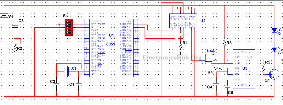
Components Included in this Transmitter Circuit:
List of components and the corresponding values are shown below –
- R1 – 1M
- R2 – 10k
- R3 – 760Ohms
- R4 – 1.5K
- R5 – 100Ohms
- C1, C2 – 15pF
- C3 – 10uF
- C4 – 0.01uF
- C5 – 0.1uF
- S1 – 5 DIP switch
- V1 – 5V
- U1 – AT89C51
- U2 – HT12E
- U3 – LM555
- U4A – 7408 (AND gate)
- Q1 – BC547
How to Operate the Transmitter Circuit?
When the circuit is powered, the compiler with initialize the stack pointer and other variables and calls the main function. It scans the input pins, i.e. the signals from the switch.
In case any of the switches is pressed, as per the program, the compiler assigns the corresponding 4 bit value to 4 pins of the output port, i.e. The required 4 bit output signal is generated which is fed to the data input of the encoder.
The encoder then converts this 4 bit parallel data into serial data, i.e. generates a code for each parallel data input. The output from the encoder is connected to the reset pin of the time 555 such that the timer will operate only when there is any output from the encoder. The timer produces a 38KHZ signal used to drive the IR LEDs, thus producing a modulated 38 KHz IR signal.
Receiver Circuit Diagram:

- 5 Channel Remote Control – Receiver Circuit
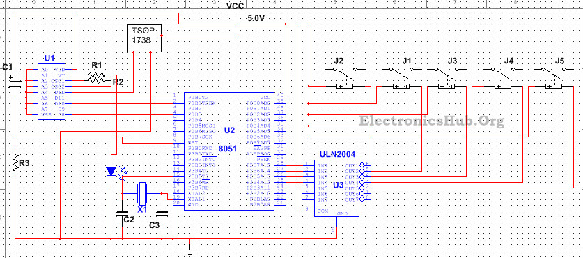
Components Included in this Receiver Circuit:
List of components and the corresponding values are shown below –
- R1 – 100Ohms
- R2 – 50K
- R3 – 10K
- C1 – 10uF
- C3, C2 – 10uF
- V1 – 5V
- U1 – HT12D
- U2 – AT89C51
- U3 – ULN2004
- Q1 – BC547
- J1, J2, J3, J4, J5
How Receiver Circuit Works?
The transmitted IR signal is received by the TSOP 1738 or the IR receiver, which demodulates the signal using an arrangement of pin diode and filter. Output from the receiver is fed to the input of the decoder which initially checks the received data at least three times and then sends a high pulse to the VT pin so as to indicate a valid transmission. The decoder then converts the serial data input into 4 bit parallel data output. In the mean time, the microcontroller gets booted and the input pins are scanned. For a certain 4 bit input signal, the compiler assigns a high logic signal to the corresponding input pin of the relay driver. The relay driver ULN2004 is actually a Darlington array IC which shifts the voltage level of the received input signal so as to provide a low voltage signal at the corresponding output pin. The relay coil connected to that output pin thus gets energized as current flows through it and armature moves from its original position so as to complete the circuit and the lamp starts glowing (not shown in the picture). This operation is same for switching on all other lamps.
Applications of 5 Channel IR Remote Control Circuit:
- This circuit can be used to drive number of loads like lamps.
- This circuit can be modified to drive a toy vehicle or a robot using a motor driver instead of a relay driver.
Limitations of 5 Channel IR Remote Control Circuit:
- This project uses IR transmission which is of low range and requires line of sight communication.

25 Responses
thanks ,itis very good
good
its very useful to me for doing this experiment i like most its good
its a very good one
but I’m kindly asking if I can get the modified circuit diagram that operates toys like .model aircrafts plz
or wat modification is to b made
can anyone provide me the source code for this project?
manohar did u get that programming for 5 channel remote control circuir if yes please send me
please give me programming for 5 channel ir remote control
thanks! its very useful…
Wow
WHAT COMPONENT IS LABELLED “x1”?
It is a crystal oscillator
x1 crystal is not mentioned is it 11.0592 Mhz
can RF be used in place of IR
Can be used this circuit for rf remote
please send me source code ( programme ) for IR remote controle switch using microcontroller
my e mail ID is ” pankajscience4884@gmail.com“
wher program code?
where program code?
Pls I need a code for writing a program of that nature using PIC16f877 for both the transmitter and receiver. thanks
Sm1 plz post the 8051 code for both transmitter and reciever…Thanks
Please give me code of the project?
can i have the code?
Can i get the code for transmitter as well as receiver
please anyone send me code (program) for above project reciever as well as transmitter on my email id– krishangarg2011@gmail.com
Can I add extra 2 more ir receiver
Have you source code for above project.