Audio Amplifiers are being used for decades. The main function of an audio amplifier is to reproduce the input audio signal at sound producing systems like speakers with desired volume and power levels.
The frequency range of audio signals is between 20Hz and 20,000Hz. Hence, the audio amplifier must have good frequency response over the above range.
The power capability of an audio amplifier are dependent on the application. Headphones require a few milliwatts of power, TV and PC audio requires few watts to tens of watts while powerful home theatres and commercial sound systems like theatres and auditoriums require few hundreds of watts.
A 200W Audio Amplifier is implemented in this project. It can be used to drive high power speakers of 4 to 16Ω.
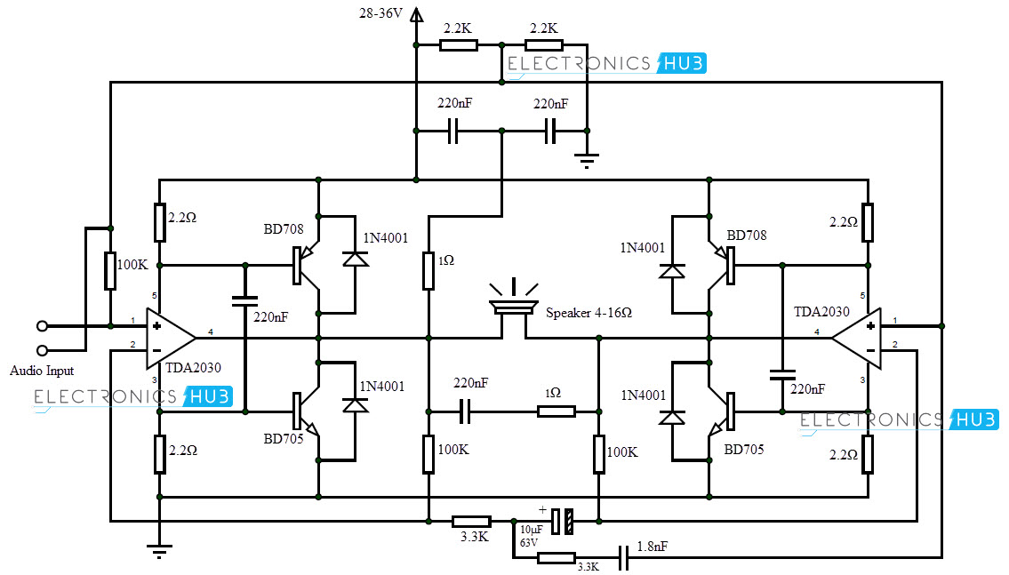
200Watt Audio Amplifier Circuit Diagram
Components Required
- TDA2030
- BD708
- BD705
- 220nF
- 1.8nF
- 10µF/63V Electrolytic
- 100KΩ
- 3.3KΩ
- 2.2KΩ
- 2.2Ω
- 1Ω
- 1N4001
Component Description
TDA2030
It is a 14W class AB amplifier. It is a 5 pin IC. It can provide a continuous power of 12W to a 4Ω load and a power of 8W to an 8Ω load.
BD708 and BD705 (NPN and PNP)
They are complimentary power transistor pair generally used in power switching applications. The maximum power dissipation is 75W.
Circuit Design of 200W Audio Amplifier
TDA2030 is a 14W Hi-Fi audio amplifier. A single TDA2030 amplifier IC can be used to drive a small speaker without any transistors.
Two TDA2030 amplifiers can be connected in a bridge fashion to get a maximum power of 28W to drive an 8Ω load. But in order to get a continuous power of 200W, we need to connect power transistors.
Hence, two complimentary Power transistor pairs consisting of BD708 (NPN) and BD705 (PNP) are connected in the bridge configuration.
The Power transistors are rated with a power dissipation of 75W. Hence, we can get a peak instantaneous power of 300W. A suitable speaker of at least 150W power can be used with a load resistance between 4Ω and 16Ω.
Working
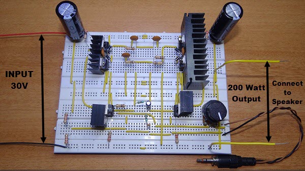
- The audio amplifier implemented in this project can produce a power of 200W. The working of the circuit is mentioned below.
- The input audio signal is given to TDA2030. A reference input is given to second TDA2030.
- The input signal is amplified by the TDA2030 IC. This output is given to inverting terminal via feedback.
- The output of the amplifier is given to four power transistors that are used to raise the power of the signal to 200W. This power amplified audio signal is given to suitable speakers.
- The volume levels of the amplifier can be controlled by using a POT at the input (not shown in the circuit).
Power Supply Requirements
- Since it is a power audio amplifier, the power supply to the circuit is an important factor in the design. Also, the power consumption of the audio amplifier circuit may increase up to 5 Amps.
- If the power supply used in the circuit is a un stabilized one, it is advised to use a 28V transformer. In this case, a power of 120W at a 4Ω speaker is shown.
- In order to use the complete power of the amplifier, a stabilized power supply of 36V and 5A must be used.
- The power supply must be properly filtered with capacitors of minimum 10,000µF/50V.
Note
The temperatures of ICs (TDA2030) and transistors (BD708 and BD705) may be very high during operation.
It is very important that all the sensitive components like ICs and transistors must be placed on individual heat sinks with mica insulation. A cooling fan must be used to lower the temperatures.
The PCB design of the high power audio amplifier is very important and must be designed with enough room for heat dissipation for all the components.

10 Responses
How much watts for 1 & 2.2 ohm resistor?
They are 1/2 watt resistors
can i have pcb layout for this pls.
seems very good circuit. can i replace tda2030 with lm1875 here.
thanks
We will update it soon
Is it really possible to get 200w from single supply? (ie 30v, because most of the high power amplifier needs split supply)
Not necessarily split supply is always required. Power is calculated using formula voltage square divided by resistance load multiplied by 2 to cater for all types of losses.
Is it going to be a center-tape transformer?
Hi,is it possible to use TDA2030A instead of TDA2030